Connecting the usb-quad08 to your system, Signal connections – Measurement Computing USB-QUAD08 User Manual
Page 9
USB-QUAD08 User's Guide
Installing the USB-QUAD08
9
Connecting the USB-QUAD08 to your system
To connect the USB-QUAD08 to your system, turn on your computer and connect the USB cable to an
available USB port on the computer or to an external USB hub connected to the computer. Connect the other
end of the USB cable to the USB connector on the device.
When you connect the device for the first time, a
Found New Hardware
dialog opens when the operating
system detects the device. Two drivers will be loaded — "MCC USB" and "USB-QUAD08". The installation is
complete after the drivers are loaded and the dialog closes. The Status LED on the USB-QUAD08 should blink
and then remain on, indicating that communication between the device and the computer is established.
The
Power
LED blinks during device detection and initialization, and then remains on. When first powered on,
a momentary delay may occur before the Power LED begins to blink or become solid.
If the Status LED turns off
If the Status LED turns on but then turns off, the computer has lost communication with the USB-QUAD08. To
restore communication, disconnect the USB cable from the computer, and then reconnect it. This should restore
communication, and the LED should turn on.
Signal connections
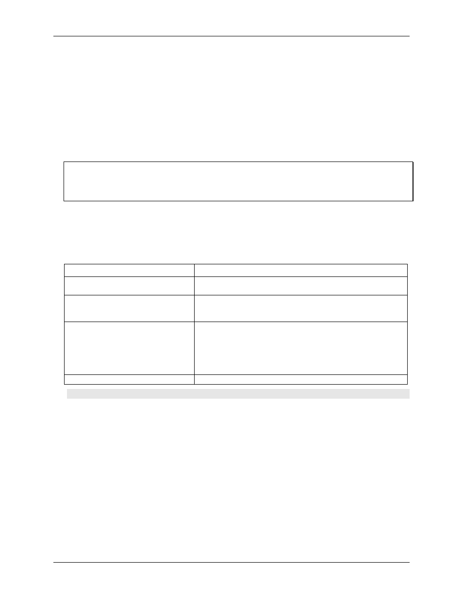
The USB-QUAD08 has 10 screw terminals and two 37-pin connectors. The table below lists the board
connectors, applicable cables, and accessory products compatible with the USB-QUAD08.
Board connectors, cables, and accessory equipment
Connectors, cables, and accessories
Description
Connector type
10 banks of detachable screw terminals
Two 37-pin D type connectors — J12 (external) and J50 (internal)
Compatible cables with the 37-pin
connectors
C37F-4X9F-1M
C37FF-x
C37FFS-x
Compatible accessory products
with the C37FF-x cable or C37FFs-x cable
CIO-MINI37
SCB-37
CIO-MINI37/DST
CIO-MINI37-VERT
CIO-MINI37-VERTDST
CIO-TERMINAL
Wire gauge range for screw terminals
16 AWG to 28 AWG
Caution! Be sure to correctly phase the encoder according to the manufacturer instructions.