Trigger and pacer, Indicator leds – Measurement Computing USB-QUAD08 User Manual
Page 30
USB-QUAD08 User's Guide
Specifications
30
Digital I/O
– Timer outputs – Terminal count outputs
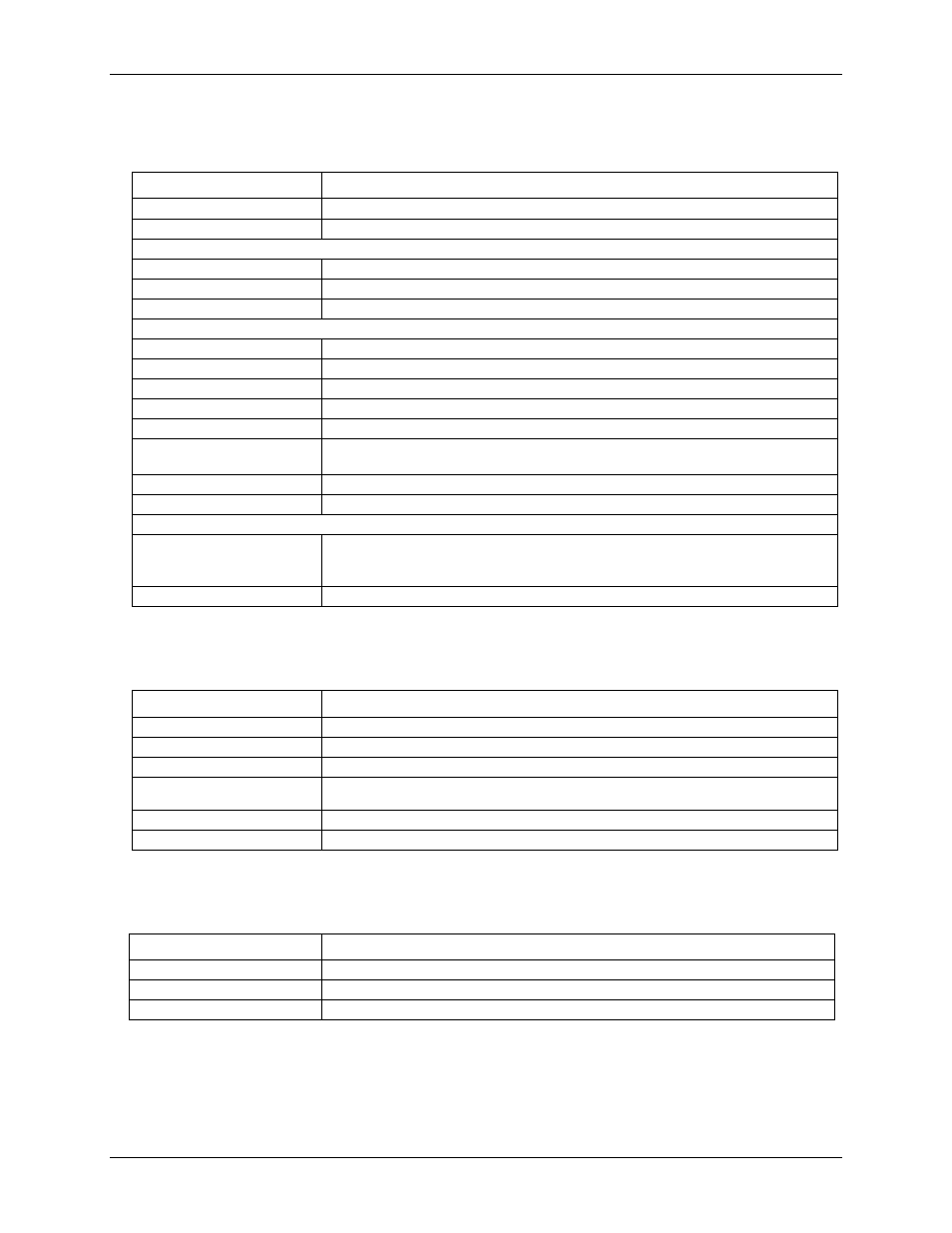
Table 3. Output specifications
Parameter
Specification
Number of I/O
8 independent
Configurable
Timer outputs (DIO6, DIO7 only), Terminal count/Modulo, Input/Output (default)
Input:
Input characteristics
Weak 10 kΩ resistor pulled-up to 5V with protection diode (+V
USB
– diode drop).
Input high
+2.0 V to 42.4 V
pk
50 VDC
Input low
0 V to 0.8 V
Output:
Output characteristics
Open-collector Darlington transistors with CEMF suppression diodes (ULN2803)
Output logic supply
User voltage supply up to 50 VDC (42.4 V
pk
) for strong drive.
CEMF Supply (CLMP+)
Connect to logic supply positive terminal up to 50 VDC (42.4 V
pk
)
Output high
2.0 VDC to 50 VDC (42.4 V
pk
); dependent upon logic supply.
Output low
<0.8 V
Output sink current
500 mA per pin, 2.5 A max. per device (parallel connections for higher current needs)
requires external supply.
Output generation
Counter events or timer outputs (bits 6 and 7); asynchronous generation
Asynchronous throughput
4000 updates/second, typ (tested on Windows XP and Windows Vista32)
Timer outputs:
Number of channels
Two 16-bit
Timer Output 0 (DIO6)
Timer Output 1 (DIO7)
Effective frequency range
0.01123 Hz to 5 MHz
Trigger and pacer
Table 4. Trigger and pacer specifications
Parameter
Specification
Digital type
Edge/level sensitive; software-selectable.
Trigger types
Start acquisition process
Pacer
Latch counter values for read back
Trigger and pacer inputs
Internal (software)
External
Trigger and pacer input
–0.5 V to 7.0 V
External pacer frequency
8 MHz, max
Indicator LEDs
Table 5. LED specifications
Parameter
Specification
Power LED
Indicates that the device’s microcontroller has power and is running.
Status LED
Indicates that the USB is configured; blinks to indicate USB traffic.
Channel LEDs
Indicates that the encoder/counter is receiving a valid signal on any of the inputs.