Specifications, Counter, Input – Measurement Computing USB-QUAD08 User Manual
Page 29: Chapter 4
29
Chapter 4
Specifications
All specifications are subject to change without notice.
Typical for 25 °C unless otherwise specified.
Specifications in italic text are guaranteed by design.
Counter
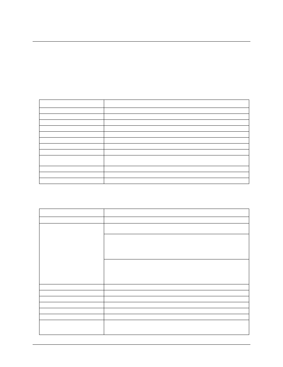
Table 1. Counter specifications
Parameter
Specification
Counter type
FPGA
Counters
8 (quadrature or normal)
Counter input modes
Quadrature (x1, x2, x4)/Totalize, Pulse width, Period
Mode options
Non-Recycle, Range Limit, Clear on Read, Modulo-N, Up/Down, Decrement
Index options
Latch, Clear|Reload, Decrement, Gate; mode dependent.
Resolution
16, 32 or 48-bit counters
Quadrature mode input frequency
10/5/2.5 MHz, max, in x1/x2/x4
Normal mode input frequency
10 MHz, max
De-bounce times
16 steps from 500 ns to 25 ms; positive or negative edge sensitive; glitch detect
mode or de-bounce mode; software-selectable.
Time-base and accuracy
48 MHz (24 MHz – 30 ppm with a 2xDLL (delay locked loop))
Counter read pacer
Internal or external scan pacer up to 8 MHz
Period/pulse width resolution
20.83 ns; 208.3 ns; 2.083 µs; or 20.83 µs
Input
Table 2. Input specifications
Parameter
Specification
Receiver type
SN75ALS175 quad differential receiver
Configuration
8 channels. Each channel consists of PhaseA input, PhaseB input and Index input;
each input is selectable as single-ended or differential.
Differential:
PhaseA, PhaseB and Index (+) inputs at the user connector are routed to the
(+) inputs of differential receiver.
PhaseA, PhaseB and Index (–) inputs at the user connector are routed to the
(–) inputs of the differential receiver.
Single-ended:
PhaseA, PhaseB and Index (+) inputs at the user connector are routed to the
(+) inputs of the differential receiver.
PhaseA, PhaseB and Index (–) inputs at the user connector are left floating.
The (–) inputs of the differential receiver are routed to the +3 V reference.
Common mode input voltage range
±12 V
Differential input voltage range
±12 V
Input sensitivity
±200 mV
Input hysteresis
50 mV, typ
Input impedance
12 kΩ, min
Absolute maximum input voltage
±14 V, max
Miscellaneous
Meets or exceeds ANSI EIA/TIA-422-B, EIA/TIA-423-B, RS-485.
Meets ITU recommendations V.10, V.11, X.26, X.27.
Designed for multipoint busses on long lines and in noisy environments.