Configuring the channel input mode, Installing the hardware – Measurement Computing USB-QUAD08 User Manual
Page 8
USB-QUAD08 User's Guide
Installing the USB-QUAD08
8
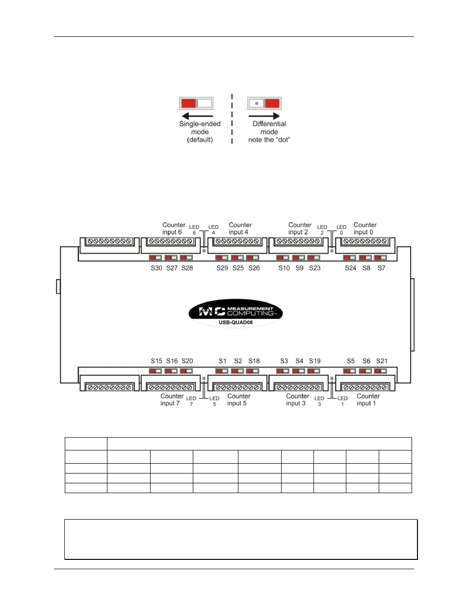
Configuring the channel input mode
The counter inputs are configurable as single-ended (±12 V ) or differential (±12 V; differential input ±14
Vmax) mode via on-board switches (see Figure 1).
Figure 1. Channel input mode switch
Figure 2 shows the locations for the counter input mode switches and the counter LEDs. Using the board
orientation shown in Figure 2, slide the switch to the left (toward the USB connector) for single-ended mode, or
to the right (towards the 37-pin connector) for differential mode. Note that the "dot" is visible on the switch
when configured for differential mode, regardless of the board orientation.
By default, the board is shipped with the counter inputs configured for single-ended operation (as shown in
Figure 2).
Figure 2. Input mode switch and LED locations
The following table lists the counter input channel associated with each switch.
Counter input channel
Input
0
1
2
3
4
5
6
7
Phase A
S7
S5
S23
S3
S26
S1
S28
S15
Phase B
S8
S6
S9
S4
S25
S2
S27
S16
Index
S24
S21
S10
S19
S29
S18
S30
S20
Installing the hardware
Install the MCC DAQ software before you install your board
The driver needed to run your board is installed with the MCC DAQ software. Therefore, you need to install the
MCC DAQ software before you install your board. Refer to the Quick Start Guide for instructions on installing
the software.