Measurement Computing USB-QUAD08 User Manual
Page 36
USB-QUAD08 User's Guide
Specifications
36
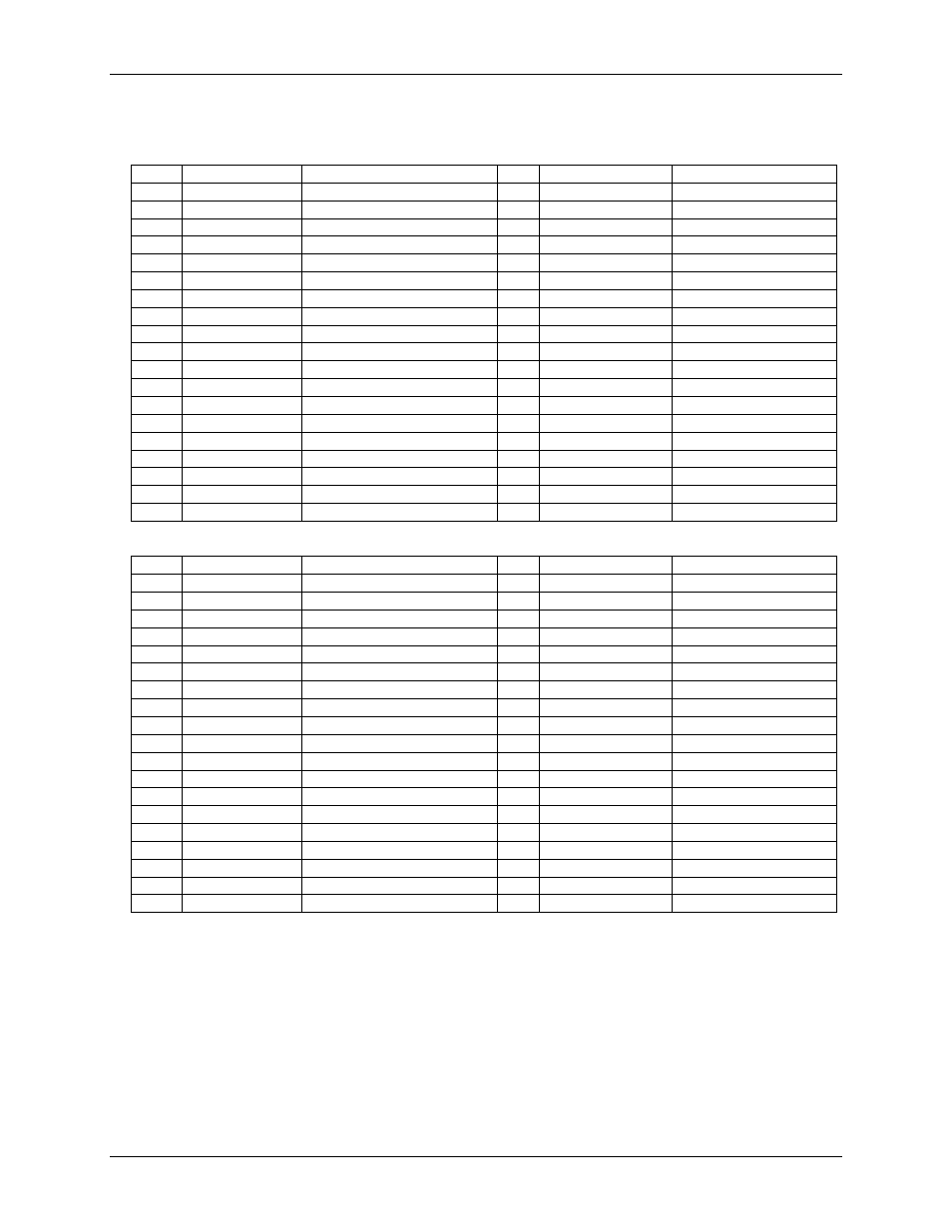
J50
Table 15. Differential mode pinout
Pin
Signal name
Pin description
Pin
Signal name
Pin description
1
4PHA
–
Counter 4 Phase A low
20
4PHA+
Counter 4 Phase A high
2
ENC+
Encoder power output
21
4PHB+
Counter 4 Phase B high
3
4PHB
–
Counter 4 Phase B low
22
GND
Ground
4
ENC+
Encoder power output
23
4INDX+
Counter 4 Index high
5
4INDX
–
Counter 4 Index low
24
6INDX
–
Counter 6 Index low
6
NC
No connection
25
6PHA+
Counter 6 Phase A high
7
6PHA
–
Counter 6 Phase A low
26
6PHB+
Counter 6 Phase B high
8
ENC+
Encoder power output
27
GND
Ground
9
6PHB
–
Counter 6 Phase B low
28
6INDX+
Counter 6 Index high
10
ENC+
Encoder power output
29
7INDX
–
Counter 7 Index low
11
7PHA
–
Counter 7 Phase A low
30
7PHA+
Counter 7 Phase A high
12
ENC+
Encoder power output
31
7PHB+
Counter 7 Phase B high
13
7PHB
–
Counter 7 Phase B low
32
GND
Ground
14
ENC+
Encoder power output
33
7INDX+
Counter 7 Index high
15
5PHA
–
Counter 5 Phase A low
34
5PHA+
Counter 5 Phase A high
16
ENC+
Encoder power output
35
5PHB+
Counter 5 Phase B high
17
5PHB
–
Counter 5 Phase B low
36
GND
Ground
18
ENC+
Encoder power output
37
5INDX+
Counter 5 Index high
19
5INDX
–
Counter 5 Index low
Table 16. Single-ended mode pinout
Pin
Signal name
Pin description
Pin
Signal name
Pin description
1
4PHA
–
Floating (Note 12)
20
4PHA+
Counter 4 Phase A
2
ENC+
Encoder power output
21
4PHB+
Counter 4 Phase B
3
4PHB
–
Floating (Note 12)
22
GND
Ground
4
ENC+
Encoder power output
23
4INDX+
Counter 4 Index
5
4INDX
–
Floating (Note 12)
24
6INDX
–
Floating (Note 12)
6
NC
No connection
25
6PHA+
Counter 6 Phase A
7
6PHA
–
Floating (Note 12)
26
6PHB+
Counter 6 Phase B
8
ENC+
Encoder power output
27
GND
Ground
9
6PHB
–
Floating (Note 12)
28
6INDX+
Counter 6 Index
10
ENC+
Encoder power output
29
7INDX
–
Floating (Note 12)
11
7PHA
–
Floating (Note 12)
30
7PHA+
Counter 7 Phase A
12
ENC+
Encoder power output
31
7PHB+
Counter 7 Phase B
13
7PHB
–
Floating (Note 12)
32
GND
Ground
14
ENC+
Encoder power output
33
7INDX+
Counter 7 Index
15
5PHA
–
Floating (Note 12)
34
5PHA+
Counter 5 Phase A
16
ENC+
Encoder power output
35
5PHB+
Counter 5 Phase B
17
5PHB
–
Floating (Note 12)
36
GND
Ground
18
ENC+
Encoder power output
37
5INDX+
Counter 5 Index
19
5INDX
–
Floating (Note 12)
Note 12:
In single-ended mode, the PhaseA, PhaseB and Index (–) inputs at the user connector are left
floating. The (–) inputs of the differential receiver are routed to +3 V reference.