Connecting the usb-quad08 to an encoder – Measurement Computing USB-QUAD08 User Manual
Page 15
USB-QUAD08 User's Guide
Installing the USB-QUAD08
15
Connecting the USB-QUAD08 to an encoder
Up to eight encoders can be connected to the screw terminals (nPHA, nPHB, and nINDX, where n is the
number of the encoder (0 to 7) on the screw terminal). Up to four encoders can be connected to each 37-pin
connector (external J12 and internal J50).
Encoder inputs are configurable in differential or single-ended mode. Each A and B signal can be made as a
single-ended connection with respect to the ±12V to common ground (GND).
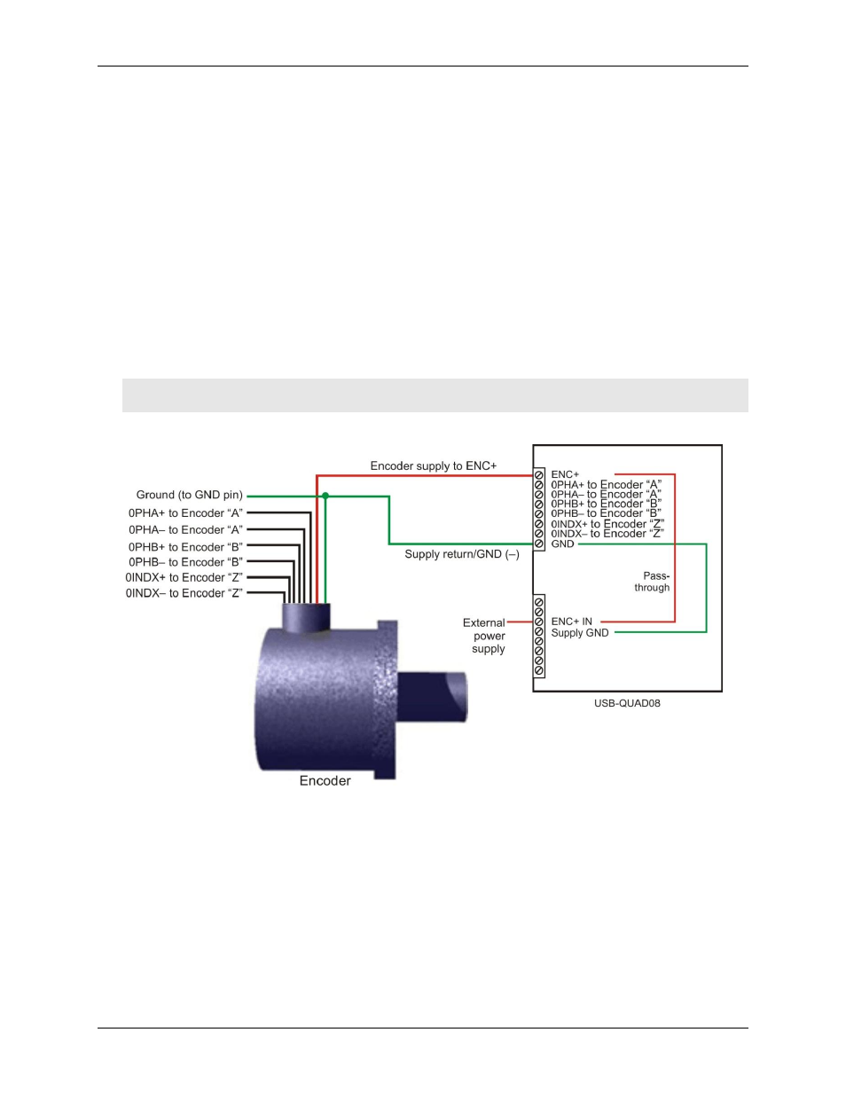
To connect the USB-QUAD08 to an encoder, make the following connections:
Connect encoder signals A, B, and Z to the A, B, and Index pins on the screw terminal or 37-pin connector.
Connect the encoder ground to a ground (GND) terminal.
Connect the encoder power supply input to an
ENC+
screw terminal.
To power the encoders, the USB-QUAD08 passes an external supply of up to 50 VDC (current rated 1.5 A
@ 5 VDC) through the
ENC+ IN
encoder power input terminal to the
ENC+
encoder
power output
terminals. Diodes protect against reverse polarity.
Connect the supply return to a ground (GND) terminal.
Caution! Ensure that the signals are connected such that there is no potential between PC ground and signal
ground. Make sure that the current output specification is not exceeded.
Figure 12 shows the differential input connections to one encoder.
Figure 12. Differential encoder connections to the screw terminal or 37-pin connector