Digital i/o, Digital input, Digital output – Measurement Computing USB-QUAD08 User Manual
Page 25: Terminal count output, Timer output
USB-QUAD08 User's Guide
Functional Details
25
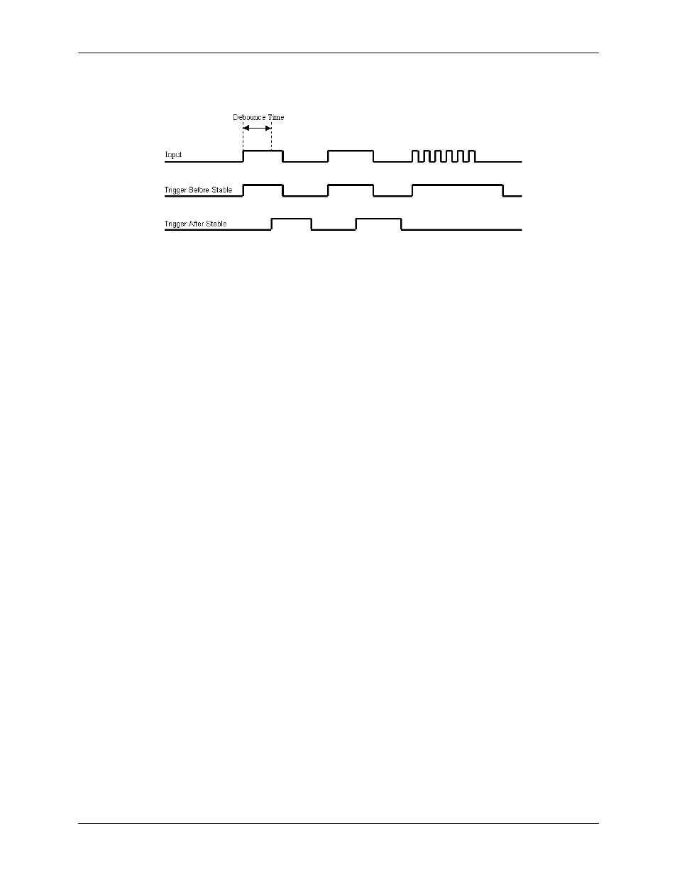
The debounce time should be set short enough to accept the desired input pulse but longer than the period of the
undesired disturbance, as shown in Figure 22.
Figure 22. Optimal debounce time for "trigger after stable" mode
Digital I/O
You can connect up to eight digital IO lines to the
DIO0
to
DIO7
screw terminals. Each digital bit can be
independently configured as a digital input, a digital output, or as a terminal count output for the corresponding
counter channel. In addition, DIO6 and DIO7 can be configured as timer outputs with variable pulse width.
When a digital channel is configured for terminal count or timer output, it cannot be used for DIO functions.
Digital input
Digital bits configured for input can accept high voltage inputs up to 42.4 V
pk
or 50 VDC. The digital inputs are
pulled high at power-up with a 10 kΩ series resistor to +5V with diode protection. This allows higher voltage
inputs from the sourcing current to the USB-QUAD08. Digital input bits are read asynchronously.
Digital output
Digital bits configured for output are open collector with an inductive diode clamped to the
CLMP+
terminal for
CEMF (counter electromotive force) suppression. DO bits can withstand 50 volts, and can operate via software
control (asynchronous). The asynchronous digital output throughput is 4000 updates/second, typical.
Terminal count output
When used as terminal count outputs,
DIO0
to
DIO7
indicate the count status for each corresponding counter
channel. The output state will go high for the period of time that the count is equal to the terminal count value
or the values specified as the MAXLIMIT.
For example, assume DIO0 is set for terminal count output. If counter 0 is configured for Range limit mode
with MAXLIMIT set to 4,096, the output of DIO0 will go high when the count reaches 4,096 (counting up) or
0 (counting down). The output remains high until counting resumes, either by a direction change or by a counter
reload.
Similarly, if configured for Modulo-N counting, the same behavior applies except that a reset or direction
change is not required to change the output state, since this mode rolls over when the MAXLIMIT value is
reached. Once the count moves off of MAXLIMIT (counting up) or 0 (counting down), the terminal count
output will go low.
Timer output
You can use
DIO6
and
DIO7
as 16-bit timer outputs. Each timer can generate a programmable pulse width wave
with a programmable frequency in the range of 0. 01123 Hz to 5 MHz. At higher frequencies, the timer output
frequency and duty cycle are dependent on the load impedance and the supply (refer to Driving digital outputs
on page 26 for more information). The duty cycle is programmable.
The timer output rate and pulse width can be updated asynchronously at any time, however, doing so results in a
pulse stream that is not seamless.