Period measurement mode, Pulse width measurement mode, Synchronous/asynchronous scanning – Measurement Computing USB-QUAD08 User Manual
Page 21: Synchronous scanning
USB-QUAD08 User's Guide
Functional Details
21
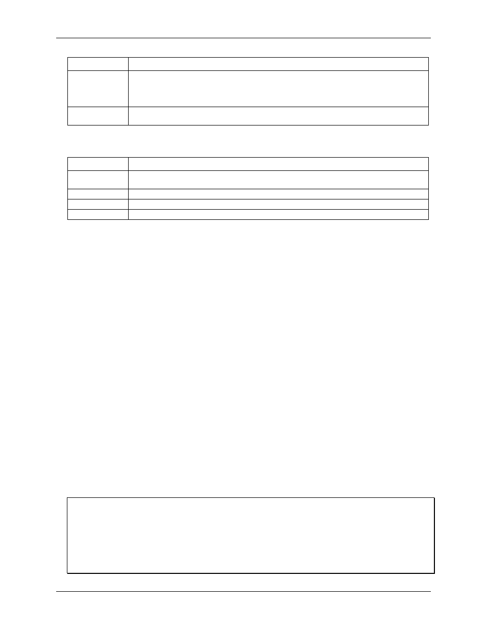
Counter mode
Description
Modulo-N
Counting up: When the maximum count (specified by the MAXLIMIT value) is reached, the counter
rolls over to 0 and continues counting up.
Counting down: When the count reaches 0, the counter rolls over to the maximum count (specified
by the MAXLIMIT value) and continues counting down.
Up/down
Up/down counting mode uses phase A as the pulse source and phase B as the direction. By default,
the counter counts up when phase B=1 (high), and counts down when phase B=0 (low).
Totalize mode options that are specific to the Index signal are listed below.
Index input mode options (Totalize mode)
Counter mode
Description
Gating
Gating mode allows the index input to gate the counter. By default, the counter is enabled when the
Index signal is high. When the Index signal is low the counter is disabled, but holds the count value.
Latching
Latching mode allows the count to be latched by the Index signal.
Clear/Reload
Clear/Reload mode allows the Index signal to reload the counter with the MAXLIMIT value.
Decrement
Decrement mode allows the Index signal to decrement the counter.
Period measurement mode
Use period mode to measure the period of a signal at a counter channel's phase A input. You can measure x1,
x10, x100 or x1000 periods, 16-bit, 32-bit, or 48-bit values. Four resolutions are available — 20.83 ns, 208.3 ns,
2.083 µs, or 20.83 µs. All period measurement mode options are software-selectable. The 48 MHz system clock
is used as the timing source. Periods from sub-microsecond to many seconds can be measured.
Counter channel inputs are read synchronously using period mode.
Pulse width measurement mode
Use pulse width mode to measure the time from the rising edge to the falling edge, or vice versa, on a signal on
a phase A counter input. Four resolutions are available (20.83 ns, 208.3 ns, 2.083 µs, or 20.83 µs). All pulse
width measurement mode options are software selectable. The 48 MHz system clock is used as the timing
source. Pulse widths from sub-microsecond to many seconds can be measured..
Counter channel inputs are read synchronously using pulse width mode.
Synchronous/asynchronous scanning
Counter inputs can be read asynchronously under program control, or synchronously as part of a digital scan
group.
Synchronous scanning
When read synchronously, the count of each channel counter is set to 0 and latched at the beginning of the
synchronous acquisition. Each clock pulse (start-of-scan signal) initiates a scan of all channels specified. Each
time the USB-QUAD08 receives a start-of-scan signal, the counter values are latched and are available to the
device. The values returned during scan period 1 are always zero. The values returned during scan period 2
reflect what happened during scan period 1. The scan period defines the timing resolution. To achieve a higher
timing resolution shorten the scan period.
Use of terminal count outputs is not recommended in conjunction with synchronous reads
When scanning is initiated, the counters are reset to 0 and disarmed until the scan begins. This has the following
affects on the terminal count outputs:
- The terminal count output timing is affected by the reset when scanning is initiated.
- When using an external trigger to initiate the synchronous acquisition, the counter is disarmed on all channels
included in the scan until the trigger occurs.
- Reloading the MAXLIMIT register interrupts the TC outputs.