Digital i/o vis, Dbitin.vi – Measurement Computing UL for NI LabVIEW User Manual
Page 70
Universal Library Virtual Instruments (VIs)
Digital I/O VIs
Digital I/O VIs
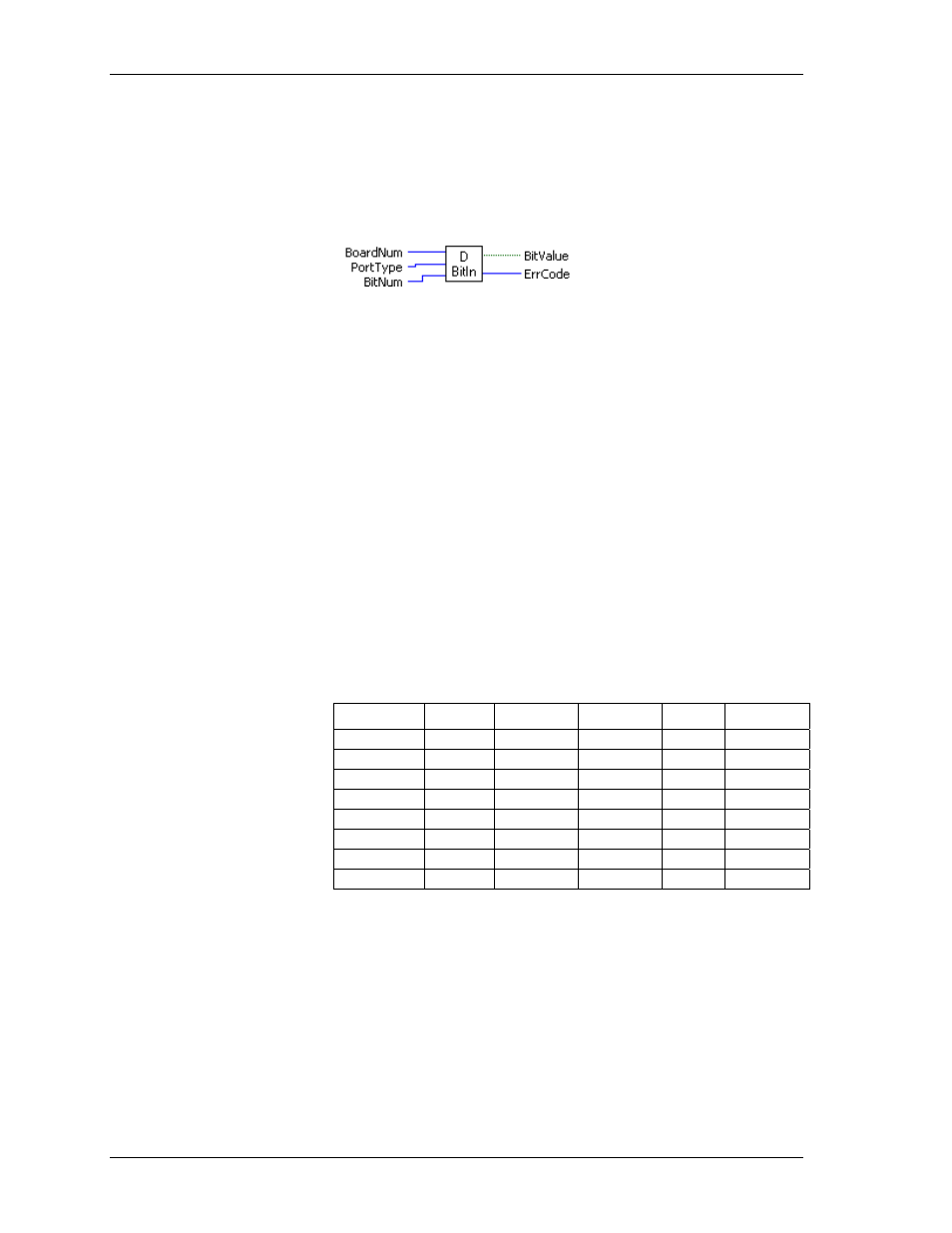
DBitIn.VI
Reads the state of a single digital input bit. This VI treats all of the digital I/O ports on a board as a single very
large port. It lets you read the state of any individual bit within this large port. If the bit or port direction is
programmable, you must first use DCfgPort.VI or DCfgBit.VI to configure the bit or port for input.
Inputs:
BoardNum
[U32] - The board number assigned when installed with InstaCal. Can
be 0 to 100.
PortType
[I32] - Specifies the type of digital port to read.
BitNum
[I32] - Specifies the bit where
BitValue
is read.
Outputs:
BitValue
[TF] - Placeholder for return value of bit - the bit's value (0 or 1)
ErrCode
[I32] - Error code. See ErrMsg.VI
Arguments:
BoardNum
The board number associated with a board when it was installed with InstaCal.
PortType
There are two general types of digital I/O: 8255 and other. Some boards (DIO
Series) use an 8255 for digital I/O. For these boards
PortType
should be set to
FIRSTPORTA
. Other boards don't use an 8255. For these boards,
PortType
should be
set to
AUXPORT
. Some boards have both types of digital I/O (PCI-DAS6025). Set
PortNum
to either
FIRSTPORTA
or AUXPORT depending on which digital inputs
you wish to read.
BitNum
Specifies the bit number within the single large port. The specified bit must be in a
port that is currently configured as an input.
The table below shows which bit numbers are in which 82C55 and 8536 digital
chips. The CIO-DIO192 supports eight 82C55 chips—the most available on a
single board. The PCI-INT32 supports two 8536 chips—the most available on a
single board.
82C55 Bit#
Chip #
Address
8536 Bit#
Chip #
Address
0 - 23
1
Base + 0
0 - 19
1
Base + 0
24 - 47
2
Base + 4
20 - 39
2
Base + 4
48 - 71
3
Base + 8
72 - 96
4
Base + 12
96 - 119
5
Base + 16
120 - 143
6
Base + 20
144 - 167
7
Base + 24
168 - 191
8
Base + 28
BitValue
Placeholder for return value of bit. Value will be 0 or 1. A 0 indicates a low
reading, a 1 indicates a logic high reading. Logic high does not necessarily mean
5 V. See the board manual for chip input specifications.
ErrCode
Error code returned from the Universal Library. Zero if no error occurred. Use the
ErrMsg VI to convert
ErrCode
into a readable string.
70