Measurement Computing UL for NI LabVIEW User Manual
Page 33
Universal Library Virtual Instruments (VIs)
Analog Input VIs
Trigger
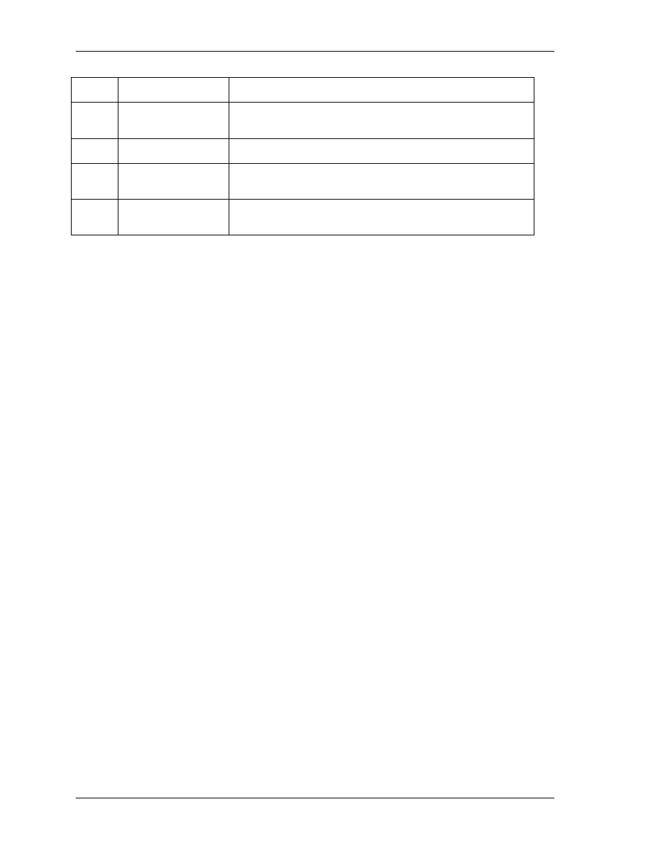
Source
Type Explanation
Digital TRIG_HIGH
A/D conversions are enabled when the external digital trigger is 5 V (logic
HIGH or "1"). After conversions are enabled, the external trigger is
ignored.
Digital TRIG_LOW
A/D conversions are enabled when the external digital trigger is 0 V (logic
LOW or "0"). After conversions are enabled, the external trigger is ignored.
Digital TRIG_POS_EDGE
A/D conversions are enabled when the external digital trigger makes a
transition from 0 V to 5 V (logic LOW to HIGH). After conversions are
enabled, the external trigger is ignored.
Digital TRIG_NEG_EDGE
A/D conversions are enabled when the external digital trigger makes a
transition from 5 V to 0 V (logic HIGH to LOW). After conversions are
enabled, the external trigger is ignored.
LowThreshold
(unsigned)
Selects the low threshold used when the trigger input is analog. The value must be
specified in counts within the range of the board's A/D trigger circuit resolution.
Refer below to "Notes."
This parameter is ignored when the trigger input is digital.
HighThreshold
(unsigned)
Selects the high threshold used when the trigger input is analog. The value must be
specified in counts within the range of the board's A/D trigger circuit resolution.
Refer below to "Notes."
ErrCode
Error code returned from the Universal Library. Zero if no error occurred. Use the
ErrMsg VI to convert
ErrCod
e into a readable string.
Notes:
The value of the threshold must be within the range of the analog trigger circuit associated with the board.
Please refer to board-specific information. For example, on the PCI-DAS1602/16 the analog trigger circuit
handles ±10 V. Therefore, a value of 0 corresponds to -10 V and a value of 65535 corresponds to +10 V.
33