Ainscfg.vi – Measurement Computing UL for NI LabVIEW User Manual
Page 21
Universal Library Virtual Instruments (VIs)
Analog Input VIs
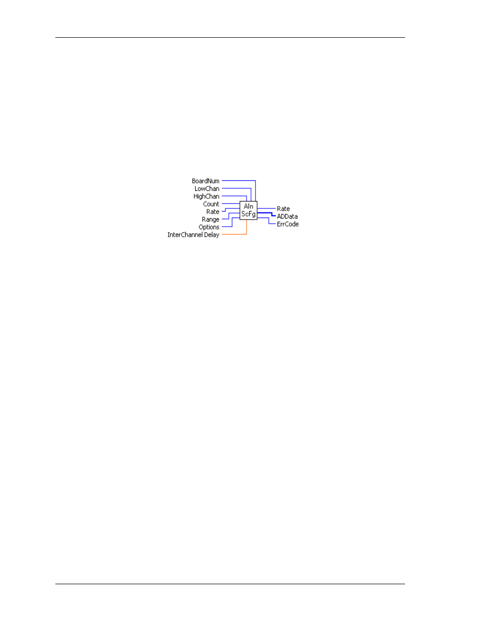
AInScFg.VI
Changed R3.3 ID, R5.4 ID
Scans a range of A/D channels in the foreground and stores the samples in an array. This VI reads the
specified number of A/D samples at the specified sampling rate from the specified range of A/D channels
from the specified board. If the A/D board has programmable gain, it sets the gain to the specified range. The
collected data is returned to the data array. This VI will not return control to your program until all requested
data has been collected and returned to ADData.
Revision 3.3: added an option to disable real-time calibration. See OptAIn.VI on page 30 for details.
Revision 5.4: added InterChannel Delay input.
Summary:
Inputs:
BoardNum
[U32] - The board number assigned when installed with InstaCal. Can
be 0 to 100.
LowChan
[I32] - First A/D channel of scan
HighChan
[I32] - Last A/D channel of scan
Count
[I32] - Number of A/D samples to collect
Rate
[I32] - Sample rate in scans per second
Range
[I32] - A/D range code
Options
[I32] - Bit fields that control various options. See Note 1.
InterChannel
Delay
[SGL]- Delay in seconds between channels in a scan.
Outputs:
Rate
[I32] - Actual rate the board sampled
ADData
[U16] - Data array that stores A/D values
ErrCode
[I32] - Error code. See ErrMsg.VI on page 97.
Arguments:
BoardNum
The board number associated with a board when it was installed with InstaCal. The
specified board must have an A/D.
LowChan
First A/D channel of scan.
HighChan
Last A/D channel of scan.
Low/High Channel
#: The maximum allowable channel depends on which type of
A/D board is being used. For boards that have both single-ended and differential
inputs, the maximum allowable channel number also depends on how the board is
configured. For example, a PCI-DAS6025 has 8 channels for differential, 16 for
single-ended mode.
Count
Specifies the total number of A/D samples that will be collected. If more than one
channel is being sampled then the number of samples collected per channel is
equal to Count / (HighChan- LowChan+1).
Rate
This is the rate at which scans are triggered. If you are sampling four channels, 0-3,
then specifying a rate of 10,000 scans per second (10 kS/s) will result in the A/D
converter rate of 40 kS/s: (4 channels at 10,000 samples per channel per second).
This is different from some software where you specify the total A/D chip rate. In
those systems, the per channel rate is equal to the A/D rate divided by the number
of channels in a scan. This argument also returns the value of the actual rate set.
This may be different from the requested rate because of pacer limitations.
21