3 signal connection, 1 connector diagram – Measurement Computing CIO-DAS16/330 User Manual
Page 9
3 SIGNAL CONNECTION
This section presents 'how to connect' common signals while avoiding discussion of electrical theory and special
symbols.
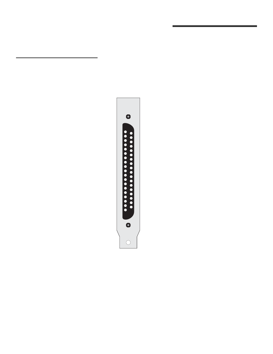
3.1 CONNECTOR DIAGRAM
The CIO-DAS16/330 analog connector is a 37-pin, D-type connector accessible from the rear of the PC through the
expansion backplate. With the exception of pins 8, 9, 10, 26 and 27 (D/A signals on the DAS-16, no connect on the
CIO-DAS16/330), the signals available are identical to the DAS-16. An additional signal, SS&H OUT, can be accessed
at pin 26.
Figure 3-1. Analog Connector
The connector accepts female 37-pin, D-type connectors, such as those on the C73FF-2, 2 foot cable with connectors.
If frequent changes to signal connections or signal conditioning is required, please refer to the information on the
CIO-MINI37 or CIO-TERMINAL screw terminal boards, CIO-EXP32 32 channel analog MUX/AMP, CIO-SSH16 16
channel simultaneous sample & hold board or the ISO-RACK08 5B isolation module interface rack.
5
LLGND 19
CH0 LOW / CH8 HIGH 18
CH1 LOW / CH9 HIGH 17
CH2 LOW / CH10 HIGH 16
CH3 LOW / CH11 HIGH 15
CH4 LOW / CH12 HIGH 14
CH5 LOW / CH13 HIGH 13
CH6 LOW / CH14 HIGH 12
CH7 LOW / CH15 HIGH 11
NC 10
NC 9
NC 8
GND 7
DIG. IN 1 6
DIG. IN 3 5
DIG. OUT 1 4
DIG. 3 OUT 3
CTR 0 OUT 2
+5V PC BUS 1
37 CH0 HIGH
36 CH1 HIGH
35 CH2 HIGH
34 CH3 HIGH
33 CH4 HIGH
32 CH5 HIGH
31 CH6 HIGH
30 CH7 HIGH
29 LLGND
28 LLGND
27 NC
26 SS&H OUT
25 DIG. IN 0 / TRIGGER
24 DIG. IN 2
23 DIG. OUT 0
22 DIG. OUT 2
21 CTR 0 CLOCK IN
20 CTR 2 OUT
37 PIN CONNECTOR