Measurement Computing CIO-DAS16/330 User Manual
Page 13
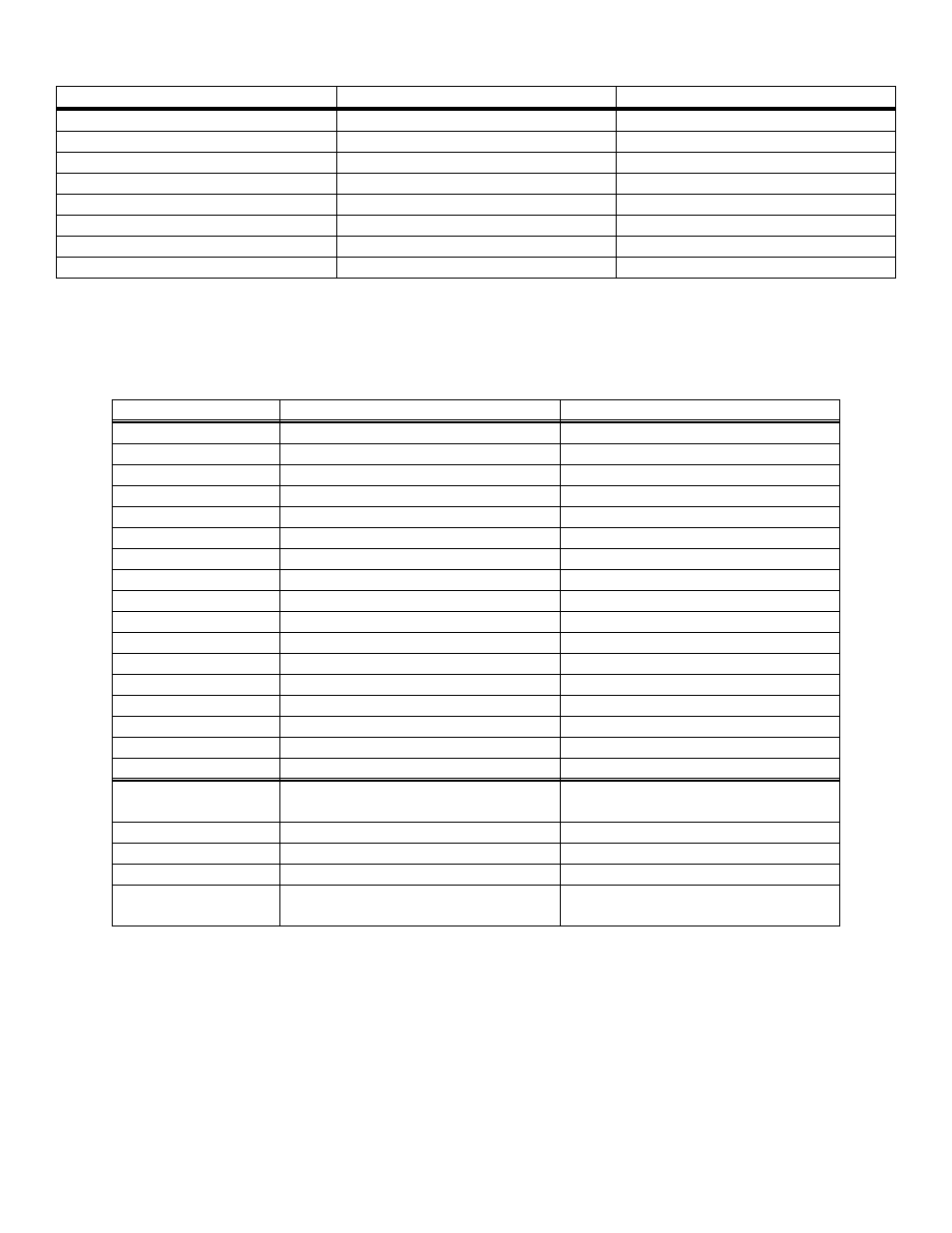
Table 4-1. Bit Weights
80
128
7
40
64
6
20
32
5
10
16
4
8
8
3
4
4
2
2
2
1
1
1
0
HEX VALUE
DECIMAL VALUE
BIT POSITION
To write control or data to a register, the individual bits are set to 0 or 1 then combined to form a Byte. The method of
programming required to set/read bits from bytes is beyond the scope of this manual.
The board registers and their function are listed on Table 4-2.
Table 4-2. Register Functions
Advanced features counter control
(8254)
None. No read back on 8254
BASE + 19
CTR 2. Pre-trigger counter
Pre-trigger count
BASE + 18
CTR 1. Total counter (1/2)
Total sample LS Counter
BASE + 17
CTR 0. Total counter (1/2)
Total sample MS Counter
BASE + 16
Upper nibble, enhanced features
control
Upper nibble, enhanced features
status
BASE + 11
ENHANCED MODE ONLY
Pacer Clock Control (8254)
None. No read back on 8254
BASE + 15
CTR 2 Data - A/D Pacer
CTR2 Data - A/D Pacer Clock
BASE + 14
CTR 1 Data - A/D Pacer
CTR 1 Data - A/D Pacer Clock
BASE + 13
Counter 0 Data
Counter 0 Data
BASE + 12
Gain, Enhanced Mode, DT Conn.
Gain setting read-back
BASE + 11
Pacer clock control register
None
BASE + 10
Set DMA, INT etc
DMA, Interrupt & Trigger Control
BASE + 9
None
Status EOC, UNI/BIP, Current Ch.
BASE + 8
None
None
BASE + 7
None
None
BASE + 6
None
None
BASE + 5
None
None
BASE + 4
Digital 4 Bit Output
Digital 4 Bit Input
BASE + 3
Channel MUX Set, Clear FIFO
Channel MUX
BASE + 2
None
A/D Bits 1 (MSB) - 8
BASE + 1
Start A/D Conversion
A/D Bits 9-12 (LSB) & Channel #
BASE
WRITE FUNCTION
READ FUNCTION - ALL MODES
ADDRESS
9