8 dma, interrupt & trigger control, 9 pacer clock control register – Measurement Computing CIO-DAS16/330 User Manual
Page 16
CH8, CH4, CH2 & CH1 are a binary number between 0 and 15 indicating the channel number that the MUX is currently
set to and is valid only when EOC = 0. The channel MUX increments shortly after EOC = 1 so may be in a state of
transition when EOC = 1. The binary weight of each bit is shown in the table above.
WRITE
A write of any data to this register resets the flip-flop on the pin 25 input and sets the INT bit to 0.
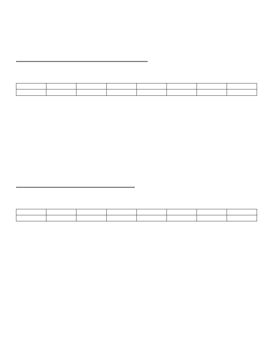
4.8 DMA, INTERRUPT & TRIGGER CONTROL
BASE ADDRESS +9
TS0
TS1
DMA
Don’t Care
IR1
IR2
IR4
INTE
0
1
2
3
4
5
6
7
A read and write register.
READ
INTE = 1, Interrupts are enabled. An interrupt generated will be placed on the PC bus interrupt level selected by IR4,
IR2 & IR1. INTE = 0, interrupts are disabled.
IR4, IR2, IR1 are bits in a binary number between 0 and 7 which map interrupts onto the PC bus interrupt levels 2 - 7.
Interrupts 0 & 1 map into interrupts 10 and 11.
DMA = 1, DMA transfers are enabled. DMA = 0, DMA transfers are disabled. It is worth noting that this bit only
allows the CIO-DAS16/330 to assert a DMA request to the PC on the DMA request level selected by the DMA
switch on the CIO-DAS16/330. Before this bit is set to 1, the PC's 8237 (or appropriate) DMA controller chip must
be set up.
TS1 & TS0 control the source of the A/D start conversion trigger according to Table 4-4.
4.9 PACER CLOCK CONTROL REGISTER
BASE ADDRESS +10
TRIG0
CTR0
X
X
X
X
X
X
0
1
2
3
4
5
6
7
Write only
CTR0 = 1. When CTR0 = 1, an on-board 100 kHz clock signal is ANDed with the COUNTER 0 CLOCK INPUT
(pin 21). A high on pin 21 will allow pulses from the on-board source into the 8254 Counter 0 input.
CTR0 = 0. When CTR0 = 0, the input to 8254 Counter 0 is entirely dependent on pulses at pin 21, COUNTER 0
CLOCK INPUT.
TRIG0 = 1. When TRIG0 = 1, the TRIGGER input at pin 25 is ANDed with TRIG0 which must be high for the
pulses from the on-board pacer clock (8254) to start A/D conversions. The input at pin 25 is pulled up and will
always be high unless pulled low externally.
TRIG0 = 0. When TRIG0 = 0, the GATEs of counter 1 & 2 are held high, preventing signals at pin 25 from gating
off the on board pacer.
12