Measurement Computing CIO-DAS16/330 User Manual
Page 11
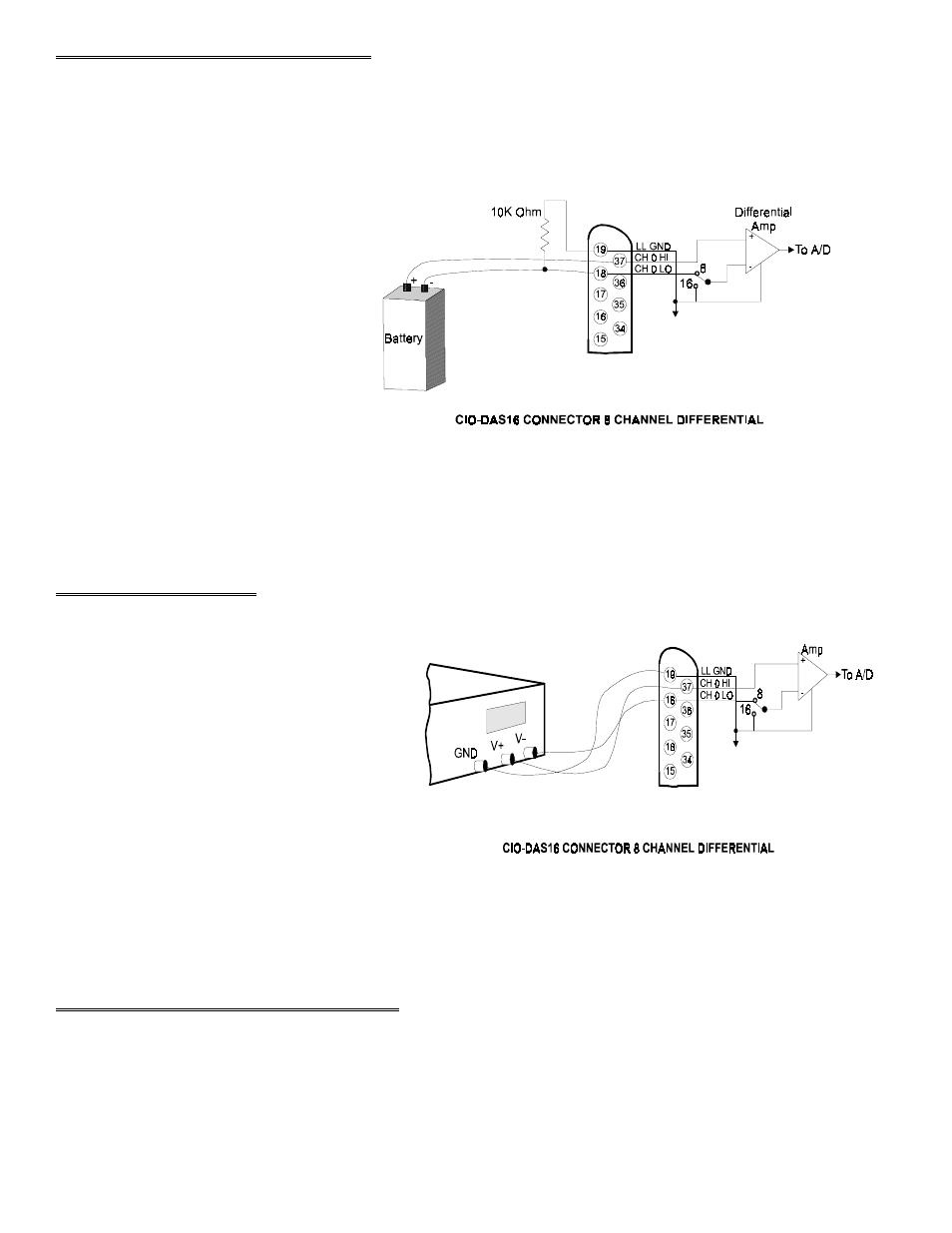
3.4 FLOATING DIFFERENTIAL
A floating differential input is two wires from the signal source and a 10K ground reference resistor installed at the board
input. The two signals from the signal source are Signal High (CH# HIGH) and Signal Low (CH# LOW).
The reference resistor is connected between the CIO-DAS16/330 CH# LOW and LLGND pins (Figure 3-3).
A floating differential hookup is handy
when the signal source is floating with
respect to ground, such as a battery,
4-20 mA transmitter or and the lead
lengths are long or subject to EMI
interference.
The floating differential input will reject
up to 10V of EMI energy on the signal
wires.
Figure 3-3. Differential Input - Floating Source
WARNING!
Is the signal source really floating? Check it with an ohmmeter before risking the board and the PC!
3.5 DIFFERENTIAL
A differential signal has three wires from the
signal source; Signal High (CH# HIGH), Signal
Low (CH# LOW) and Signal Ground (LLGND)
See Figure 3-4.
A differential connection allows you to connect
the board to a signal source with a ground that is
different than the PC ground, but has less than a
10V difference, and still make a true
measurement of the signal between CH# HIGH
and CH# LOW.
Figure 3-4. Differential Input
EXAMPLE:
A laboratory instrument with its own wall plug. There are sometimes differences in wall GND between outlets.
3.6 DIGITAL OUTPUTS & INPUTS
All the digital inputs and outputs on the CIO-DAS16/330 are TTL level. TTL is an electronics industry term, short for
Transistor Transistor Logic, with describes a standard for digital signals which are either at 0V or 5V (nominal). The
binary logic inside the PC is all TTL or LSTTL (Low power Schotky TTL).
7