Legrand RW3U600 User Manual
Page 3
CAUTION
For your safety: Connecting a proper ground to the sensor provides protection
against electrical shock in the event of certain fault conditions. If a proper ground
is not available, consult with a qualified electrician before continuing installation.
3. Prepare the Wires.
Tag the wires currently connected to the existing switch
so that they can be identified later. Disconnect the wires.
Make sure the insulation is stripped off of the wires to
expose their copper cores to the length indicated by the
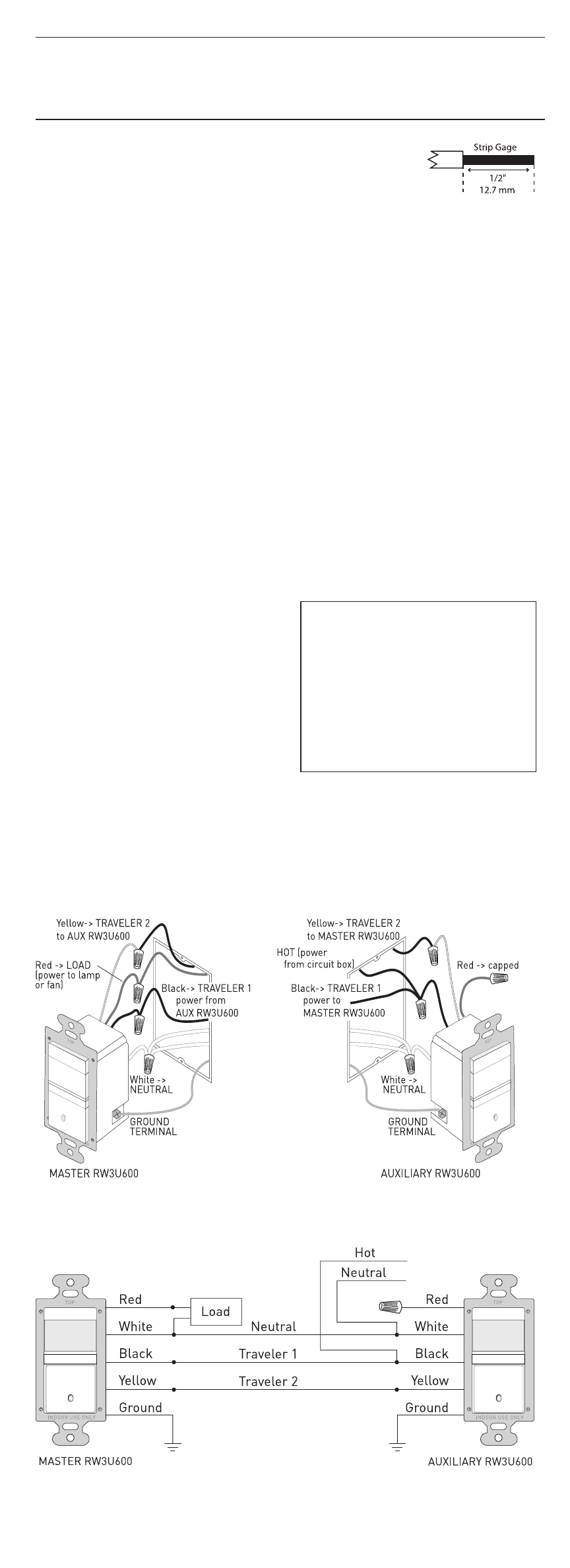
“Strip Gage,” in Fig. 3. (approx. 1/2 inch).
4. Wire the sensor.
Twist the existing wires together with the wire leads on the RW3U600 sensors as
indicated below. Cap them securely using wire nuts provided. (See Fig. 4 & 5)
• Connect the green or non-insulated (copper) GROUND wire from the circuit to
the green terminal on the RW3U600s.
• Connect the NEUTRAL wire from the circuit and from the lamp (LOAD) to the
white wire on the master RW3U600.
The term “master” designates the RW3U600 that connects to the load.
• Connect the neutral wire from the circuit to the white wire on the auxiliary RW3U600.
• Connect the power wire from the circuit box (HOT) to the black wire on the
auxiliary RW3U600 and to the TRAVELER 1 wire.
• Connect the TRAVELER 1 wire from the black wire of the auxiliary RW3U600 to
the black wire of the master RW3U600.
• Connect the lamp power (LOAD) to the red wire on the master RW3U600.
• Cap the red wire on the auxiliary RW3U600.
• Connect the TRAVELER 2 wire coming from the yellow wire of another RW3U600
to the yellow wire of the RW3U600 that you are wiring.
5. Put the RW3U600s into their respective wall boxes.
Position them with the lens positioned
above the ON/OFF button (lens at top,
ON/OFF button at bottom). Secure to
the wall box with the screws provided.
6. Make any necessary
adjustments.
See the SENSOR ADJUSTMENT &
PROGRAMMING section for information.
7. Attach the new cover plate.
Secure it with the screws provided.
8. Restore power to the circuit.
Turn on the breaker or replace the fuse.
Fig. 4: Sensor orientation, wire connections and wall box assembly
Fig. 5: Reference wiring diagram
Initial Power-up
There is an initial warm-up
period. If the sensor is in Mode 2
“Automatic ON” it may take up to a
minute before the lights turn ON.
However, the lights can be turned
ON/OFF manually by pressing the
“ON/OFF Button” at anytime when
power is supplied to the unit.
Call 800.223.4185 for Technical Support
Fig. 3: Wire
Stripping