Legrand ASTM2 User Manual
Adorne, Do n ot u se plat e ins tall ed with out a wal l
No: 340976 – 04/26 Rev. 1
adorne
TM
SensaSwitch - Manual ON/Timed OFF, SP/3W
INSTALLATION INSTRUCTIONS
Catalog Number(s): ASTM2
Country of Origin: Made in China
1
1-POLE
STRIP G
AGE
3-W
AY
WHITE
HOT
P GAG
-W
1-POLE
STRIP GAGE
HOT
INSTALLATION INSTRUCTIONS
Please read these instructions completely before you
begin. adorne
TM
switches are designed for installation in
standard electrical boxes. However, some of the installa-
tion methods vary slightly from traditional methods. If you
do not understand these instructions or are unsure of your
abilities, seek the assistance of a qualified electrician.
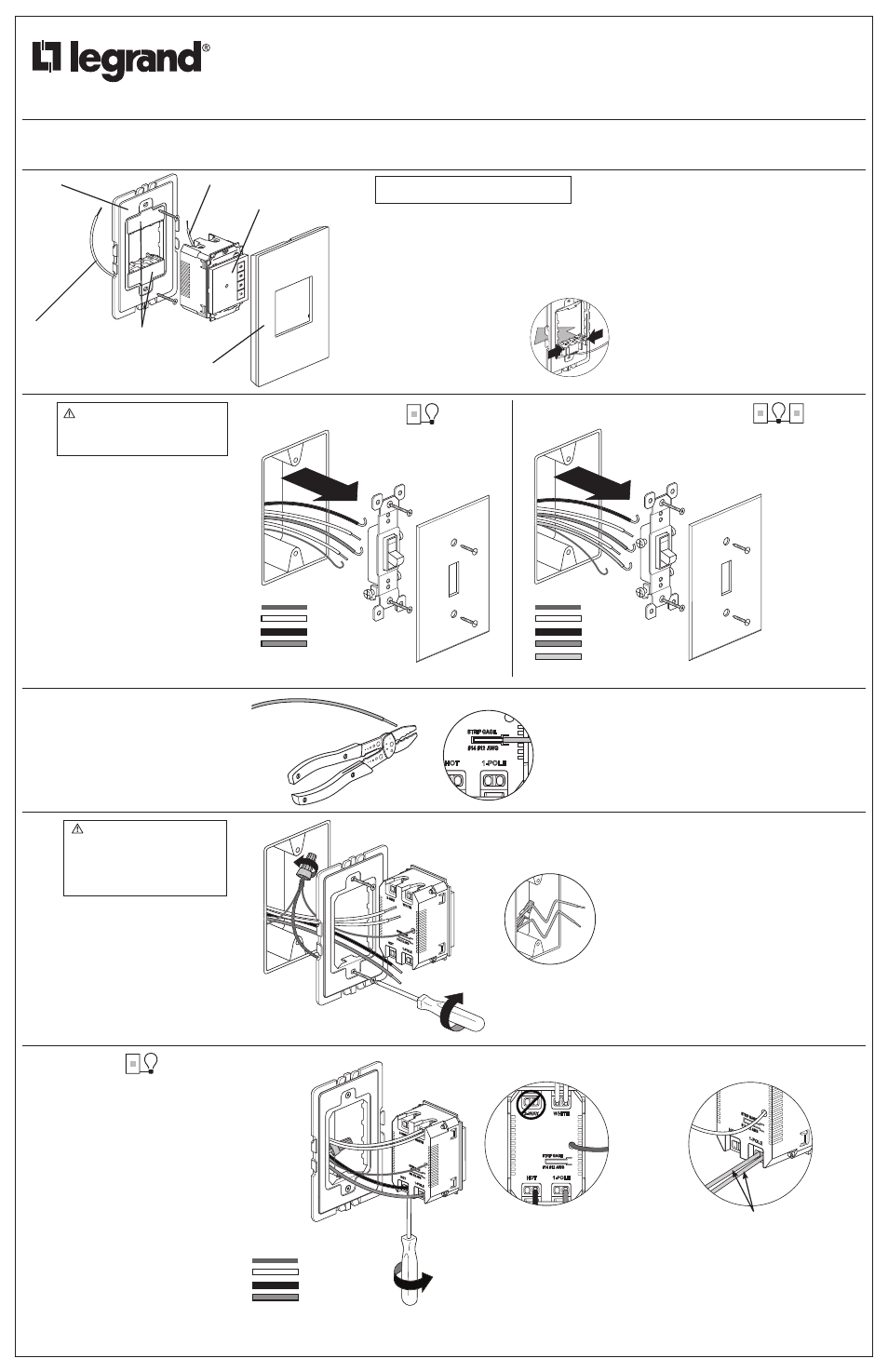
WARNING
To prevent severe shock or electrocution,
always disconnect power at the service
panel before beginning work.
3-Way
In a 3-Way circuit, Traveler wires
are the two insulated wires con-
nected to the switch that are NOT
the HOT wire that you identified
previously.
Single Pole
When replacing existing switches, label
wires before disconnecting.
Disconnect old switch.
Briefly restore power and use a line voltage
meter to identify the wires.
HOT or LINE (usually black) - runs from
service panel to switch
LOAD Runs from switch to fixture
NEUTRAL (usually white) The old switch
may not have used a NEUTRAL wire, but
it is usually available in the box.
GROUND - bare copper or Green wire
with or without yellow stripe
DISCONNECT power at the service panel
once you’ve identified the wires.
2
If necessary, cut wires and strip
insulation using stripping guide on
back of switch.
3
Connect frame ground wire and switch
ground wire to bare ground wire in box.
Fold ground wires into back of box.
Mount frame to wall box with screws
provided. Tighten screws just enough to
hold frame in place.
Do NOT over-tighten.
TIPS
• Pre-fold wires into wall box to make it easier to fit them in the
box when switch is connected.
• Use caution to avoid marring wall surface with the metal frame.
Use only with Legrand adorne
TM
system.
For more information and helpful how-to videos,
visit www.adornemyhome.com/install.
DO N
OT U
SE
PLAT
E INS
TALL
ED
WITH
OUT A
WAL
L
TOP
Remove spacers from the
frame. Since this switch fills the frame
completely, you will not need the spacers.
From the back of the frame, pinch the
tabs on the spacer to release.
SPECIFICATIONS
Voltage - 120VAC, 60Hz
Load (Single Pole or Multi-way)
Incandescent or LED lamp: 0-600 Watt
Fluorescent lamp: 0-600 VA
Fan Motor: 1/6 hp
Time Delay - 10, 20, 30, 60 minutes
Environment - Residential Indoor Use Only
Humidity - 95% RH, non-condensing
Installation Shall Be In Accordance With All
Applicable Regulations, Local And NEC Codes.
60
30
20
10
TOP
Frame
Wall Plate
Frame Ground Wire
SensaSwitch
Switch Ground Wire
Single Pole
Connect switch as shown.
Insert wires into terminals and tighten
screws securely.
• Connect LINE wire to HOT terminal on switch
• Connect LOAD wire to 1-POLE terminal
• Connect NEUTRAL from the circuit and from
lamp (LOAD) to WHITE terminal
NOTE: NEUTRAL wire is not required for
sensor to function properly.
4
Ground
Neutral
Hot/Line
Load
Ground
Neutral
Hot/Line
Load
Traveler
1-POLE
3-W
AY
WHIT
E
HOT
AY
AY
W
W
Ground
Neutral
Hot/Line
Load
1-POLE
STRIP GAGE
3-WAY
WHITE
HOT
1-POLE
STRIP G
AGE
E
HOT
NOTE:When two wires connect to
the same terminal on the sensor,
both wires must be the same gage
(12AWG or 14AWG.) If they are
not the same gage, you will not
have a secure connection
Same gage wires
Spacers
NOTE: NEUTRAL wire is not required for
sensor to function properly.
WARNING
To Reduce Risk of Electrical Shock,
unit shall be properly grounded in
accordance with NEC and Local Codes.
Failure to connect the ground wire will
result in an unsafe installation that
could lead to personal injury.