Legrand RC3APTCBK User Manual
Page 2
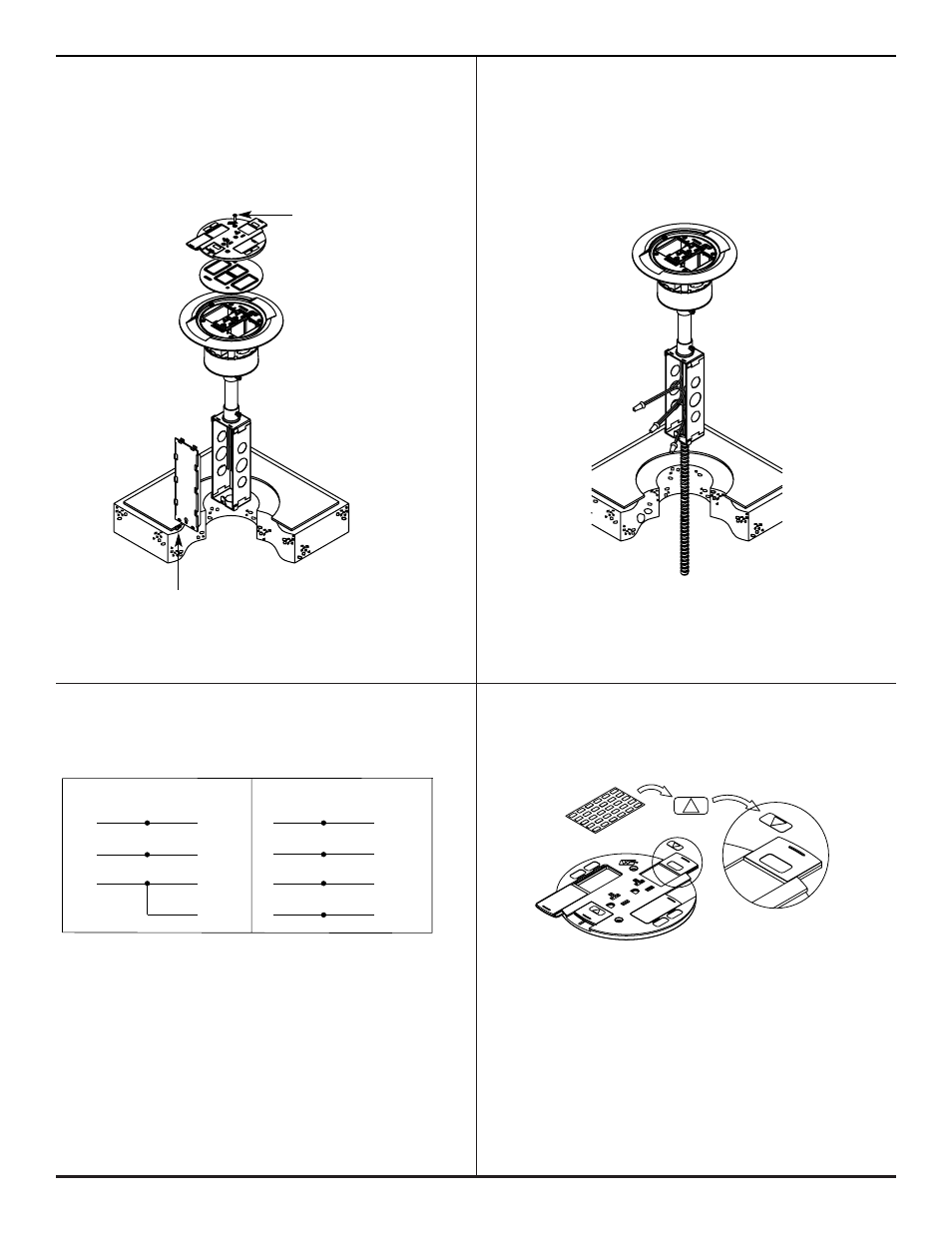
COMPLETE ASSEMBLY:
Step 6. Cat. Nos. RC3ATC or RC3ARTTC.
Step 7. Wire the power circuit.
Wire the Poke-Thru device.
(Can be completed above floor.)
Refer to wiring schematic in Step 8.
Step 8. Connect Poke-Thru conductors according
Step 9. If circuit is connected to an isolated ground,
to required device configuration. See
apply IG icon on receptacle slide as shown.
schematic below.
CAUTION: Receptacle mounting means not grounded.
NOTE: The orange triangle shall only be placed on devices
Grounding wire connection required. For isolated
that are wired for isolated ground. See NEC 250-146(d).
ground wiring; connect ground leads to a separate
isolated grounding conductor. See NEC 250-146(d).
2
Two #6-32 Slide Cover
Mounting Screws
Outlet Box
Cover Plate Screw
WHITE or NEUTRAL
from branch circuit
WHITE
from poke-thru receptacle
BLACK or HOT
from branch circuit
BLACK
from poke-thru receptacle
GREEN (jumper wire)
from poke- thru junction box
GREEN
from poke-thru receptacle
CONVENTIONAL WIRING SCHEMATIC
WHITE or NEUTRAL
from branch circuit
WHITE
from poke-thru receptacle
BLACK or HOT
from branch circuit
BLACK
from poke-thru receptacle
GREEN (jumper wire)
from poke-thru junction box
ISOLATED GROUND
from branch circuit
GREEN
from poke-thru receptacle
ISOLATED GROUND WIRING SCHEMATIC
GREEN or GROUND
from branch circuit
SYSTEM GROUND
GREEN or GROUND
from branch circuit
SYSTEM GROUND
WARNING:
Ground wire from junction box must be connected to SYSTEM GROUND.