3 manual adjustment of video signals – IHSE USA 234 Series VTO2/VRO2 KVM-Extender User Manual
Page 34
VTO2/VRO2 V.6.00 –5 STRAND KVM-EXTENDER
34
5.3 Manual Adjustment of Video Signals
CAUTION: This procedure applies to Remote Unit only with
AGC=OFF! – do not attempt any adjustment of the Local Unit.
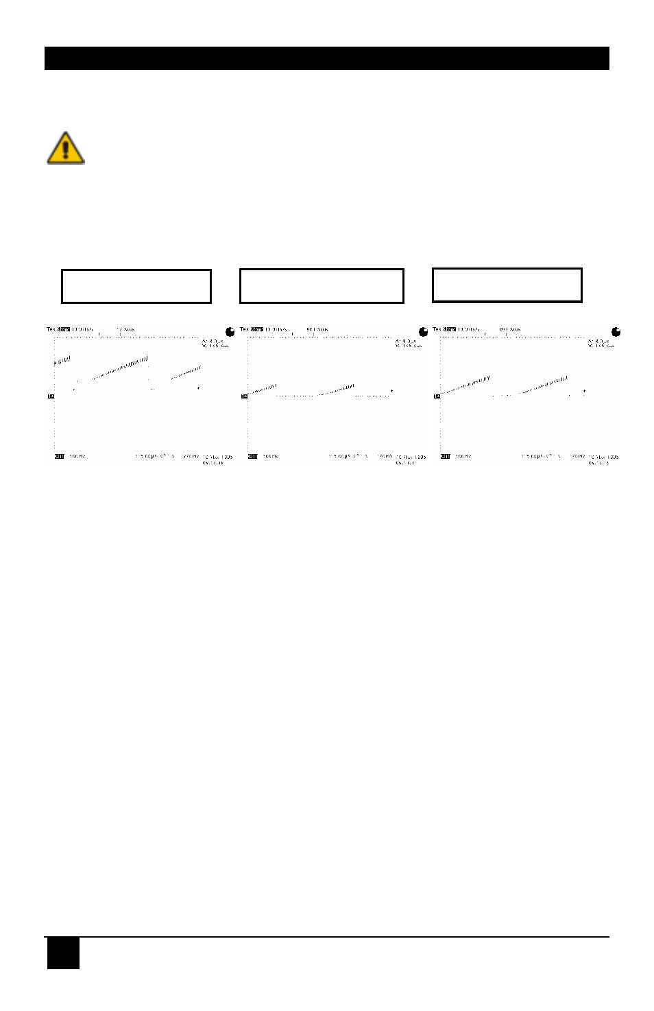
The level of the three video signals may be simultaneously adjusted with the Brightness
control. If you open too far to “brighten”, the video signal increases on oscilloscope-CRT,
and a part of the SYNC signals appears in the video signal, as shown in (a).
If you close too far to “dark”, the video signal decreases on the oscilloscope-CRT and a part
of the signal is cut: see (b).
Adjust the brightness control so that it falls just before the signal: see (c).
Adjustment of amplitude
The amplitude of the colour channels depends on:
•
The attenuation of the optical fibre
•
The attenuation of the FO-connectors
•
The position (gain) of the color control trimmer.
You may correct up to a 20% difference in signal amplitude in the three colour channels by
setting the gain with the colour control trimmer. Adjust all channels (R, G, B) to the same
value (amplitude app. 0.7Vpp...0.8Vpp = white). Since the attenuation exceeds, you may
adjust the amplitude for all channels together, using the Contrast control (see above)
A difference greater than 20% indicates either a broken fibre or FO-connector.
(a) Signal too light
(b) Signal too dark
(c) Signal OK