1 jumper location in the local unit – IHSE USA 234 Series VTO2/VRO2 KVM-Extender User Manual
Page 26
VTO2/VRO2 V.6.00 –5 STRAND KVM-EXTENDER
26
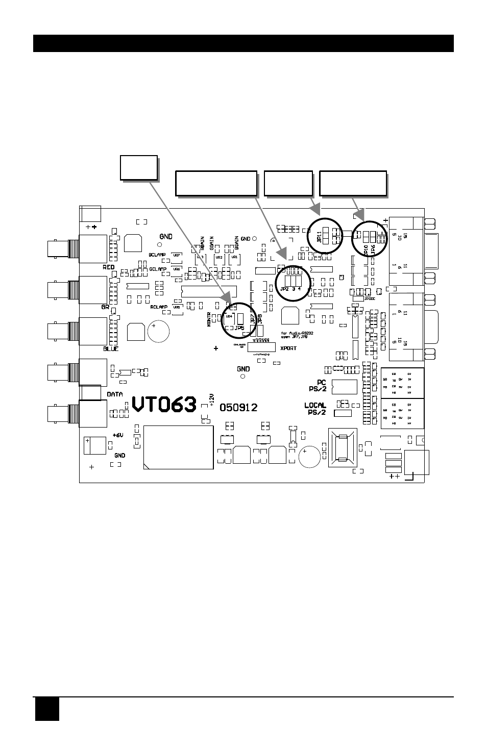
4.1 Jumper Location in the Local Unit
After unscrewing and opening the upper shell, please place the device in this orientation: with
the fibre connectors to the left and the electrical connectors to the right.
The main PCB then will look like this:
Use the diagram to locate jumpers JP2, JP3, JP4, JP5, JP6, JP10, and JP11.
JP11
JP10, JP6
JP2, JP3, JP4
JP5
This manual is related to the following products: