2 jumper location in the remote unit – IHSE USA 234 Series VTO2/VRO2 KVM-Extender User Manual
Page 27
ADJUSTMENTS
27
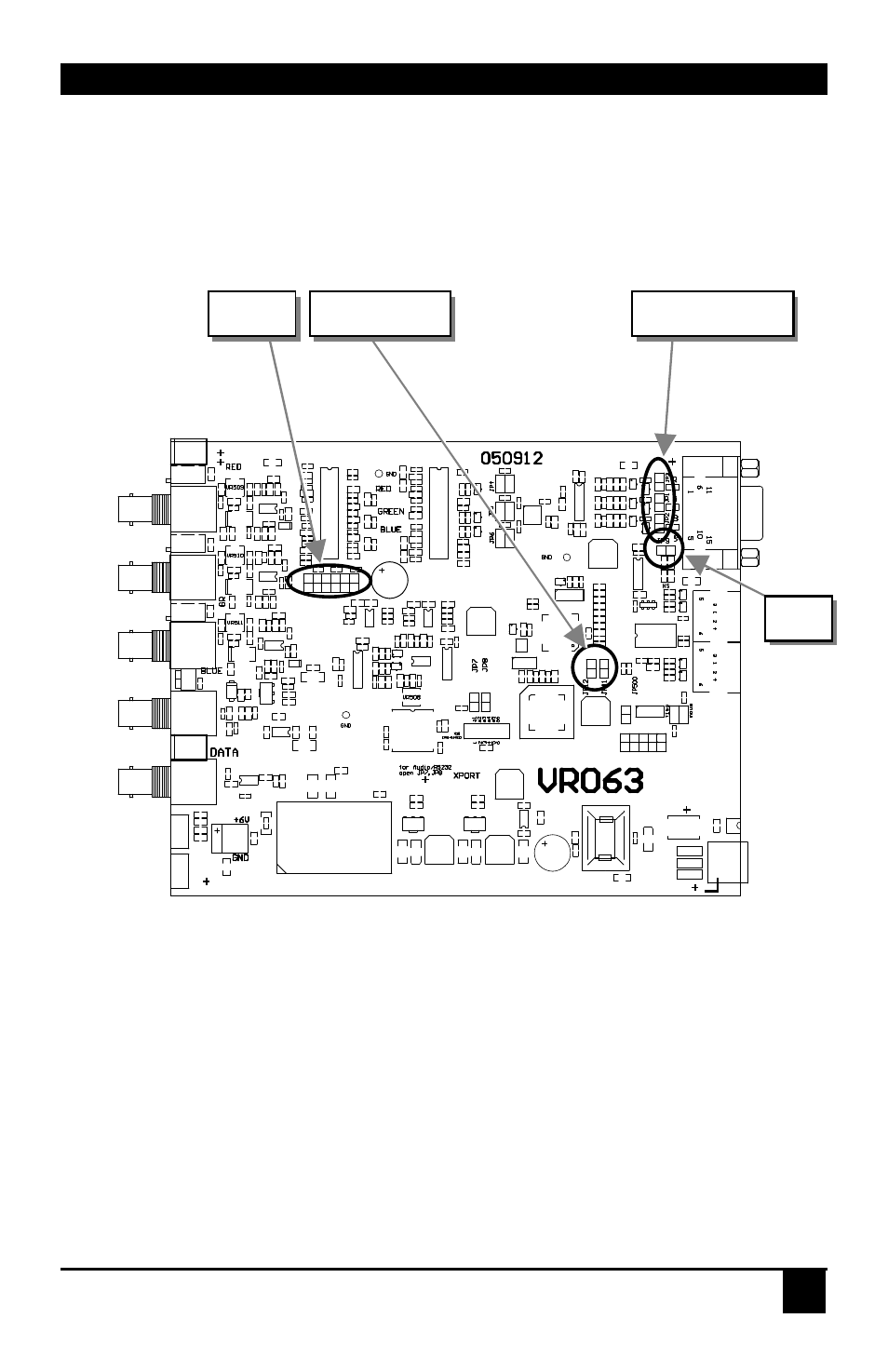
4.2 Jumper Location in the Remote Unit
After unscrewing and opening the upper shell, please place the device in this orientation: with
the fibre connectors to the left and the electrical connectors to the right.
The main PCB then will look like this:
Use the diagram to locate jumpers JP1, JP2, JP3, JP9, JP11, JP12 and JP20.Customization
You can make the following application-specific adjustments:
JP20
JP9
JP1, JP2, JP3
JP11, JP12
This manual is related to the following products: