Optional start-up components, Dirty filter switch, Economizer – Greenheck ERCH (476054) User Manual
Page 35
General Description - NOT model specific
Model ERCH Energy Recovery Ventilator
®
35
Optional Start-Up Components
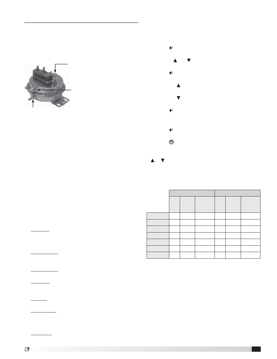
Dirty Filter Switch
To adjust the switch, the unit must be running with
all of the access doors in place, except for the
compartment where the switch is located (exhaust
intake compartment). The adjusting screw is located on
the top of the switch.
1. Open the filter compartment and place a sheet of
plastic or cardboard over 50% of the filter media.
2. Replace the filter compartment door.
3. Check to see if there is power at the alert signal
leads (refer to electrical diagram).
4. Whether there is power or not, turn the adjustment
screw on the dirty filter gauge (clockwise if you did
not have power, counterclockwise if you did have
power) until the power comes on or just before the
power goes off.
5. Open the filter compartment and remove the
obstructing material.
6. Replace the door and check to make sure that you
do not have power at the alert signal leads. The unit
is now ready for operation.
Economizer
Relevant Set Points
1. MAT SET The mixed air temperature set point after
the energy wheel. The control will modulate the
energy wheel to maintain temperature as best as it
can (Set point menu, default 53°F)
2. LOW T LOCK The set point for the low temperature
mechanical cooling lockout. (Set point menu, default
32°F)
3. DRYBLB SET The outdoor air set point to call for
economizer. (Set point menu, default 63°F)
4. MIN POS The minimum signal voltage sent to the
energy wheel. This must be set to 2 VDC. (Set point
menu, default 2.8 VDC)
5. AUX1 O The controllers operating sequence
structure. (Set point menu, default ‘None’)
6. ERV OAT SP The set point for low temperature
economizer lockout. This is the low temperature set
point when AUX1 O is set to ERV. (Set point menu,
default 32°F)
7. STG3 DLY Time delay after second cooling stage is
enabled (Advanced setup menu, default 2 hrs.)
Setscrew (on front of switch) must
be manually adjusted after the
system is in operation.
Negative pressure connection
is toward the ‘front or top’ of
the switch. (Senses pressure on
the blower side of filters)
Positive pressure connection is toward the ‘back or bottom’
of the switch. (Senses pressure at air inlet side of filters)
Using the Keypad with Settings and Parameters
To use the keypad when working with Set Points,
System and Advanced Settings, Checkout Tests, and
Alarms:
1. Navigate to the desired menu.
2. Press (enter) to display the first item in the
currently displayed menu.
3. Use the and buttons to scroll to the desired
parameter.
4. Press (enter) to display the value of the currently
displayed item.
5. Press the button to increase (change) the
displayed parameter value.a
6. Press the button to increase (change) the
displayed parameter value.a
7. Press (enter) to accept the displayed value and
store it in non-volatile RAM.
8. CHANGE STORED displays.
9. Press (enter) to return the current menu
parameter.
10. Press
(escape) to return to the current menu
parameter.
a When values are displayed, pressing and holding the
or button causes the display to automatically
increment.
The table shows which set points are relevant to the
given sequences. Refer to the wiring diagram for the
units’ sequence.
MODULATE WHEEL
STOP WHEEL
OA
Temp
OA
Enthalpy
OA/RA
Temp
Differential
OA
Temp
OA
Enthalpy
OA/RA
Temp
Differential
DRYBLB SET
X
X
MAT SET
X
X
X
X
X
X
LOW T LOCK
X
X
X
X
X
X
ERV OAT SP
X
X
X
MIN POS
X
X
X
AUX1 OUT
ERV
ERV
ERV
STG3 DLY
X
X
X
X
X
X