Start-up components, Energy wheel, Fans – Greenheck ERCH (476054) User Manual
Page 33
General Description - NOT model specific
Model ERCH Energy Recovery Ventilator
®
33
Start-Up Components
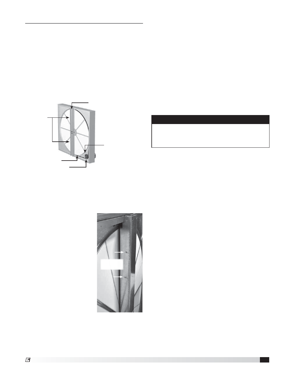
Energy Wheel
The energy wheel is installed in the unit’s airstream with
one half of the wheel in the intake airstream and one
half in the return airstream. Air leakage between the two
airstreams has to be kept to a minimum and the wheel
has air seals that must be adjusted for that purpose.
The seals must be adjusted at time of start-up.
Drive Belt
Inspect the drive belt. Make sure the belt rides smoothly
in the pulley and around the outside of the wheel. Note
the directional arrow and data information shown in the
image.
Adjust the Air Seals
The first step in wheel seal adjustment is to make sure
the unit power supply is locked out. Disconnect the
wiring to the wheel module and pull the wheel cassette
out of the cabinet on its tracks. Large cassettes are
not removable. Then slowly
rotate the wheel by hand to
make sure there is no binding
or misalignment. The wheel
should rotate smoothly and
should not bind.
There is a perimeter seal
located around the outside
of the wheel and a diameter
seal across the face of the
wheel on both sides. Check to
make sure that all air seals are
secure and in good condition.
Adjust the air seals by
loosening all the air seal
retaining screws on the
bearing support (see image for
reference). Using a piece of
paper as a feeler gauge, adjust
the seals so they almost touch
the face of the wheel while
tugging slightly on the paper. When the wheel is rotated,
there should be a slight tug on the paper. Tighten the
screws, repeat the steps on the other set of seals.
Push the wheel cassette back into the unit and plug
in the power connector. Turn the main power supply
back on and then observe the operation of the wheel by
opening the wheel access door slightly. Remove filters if
necessary to observe the wheel.
Fans
The unit contains a forward-curved supply fan and a
forward curved exhaust fan. These forward-curved
fans should be checked for free rotation. If any binding
occurs, check for concealed damage and foreign
objects in the fan housing. Be sure to check the
belt drives per the start-up recommendations in the
following section.
Centering of the fan wheel can be accomplished by
loosening the wheel hub set screw and moving the
wheel to the desired position.
Fan Performance Modifications
Due to job specification revisions, it may be necessary
to adjust or change the sheave or pulley to obtain the
desired airflow at the time of installation. The start-up
technician must check blower amperage to ensure that
the amperage listed on the motor nameplate is not
exceeded. Amperage to be tested with access doors
closed and ductwork installed.
Fan Belt Drives
The fan belt drive components, when supplied by
manufacturer, have been carefully selected for the
unit’s specific operating condition. Utilizing different
components than those supplied could result in unsafe
operating conditions which may cause personal injury or
failure of the following components:
• Fan Shaft
• Bearings
• Motor
• Fan Wheel
• Belt
Tighten all fasteners and set screws securely and realign
drive pulleys after adjustment. Check pulleys and belts
for proper alignment to avoid unnecessary belt wear,
noise, vibration and power loss. Motor and drive shafts
must be parallel and pulleys in line (see diagrams in Belt
Drive Installation section).
Bearing Support Bar
Showing air seal assembly
t
Ret
a
ain
ng
in
Scr
cr
ews
s
Label showing
cassette serial number
and date code
Bearing Support
Adjustable
Air Seals
Drive Belt
Drive Pulley
CAUTION
When operating conditions of the fan are to be
changed (speed, pressure, temperature, etc.), consult
manufacturer to determine if the unit can operate
safely at the new conditions.