Gasboy RS-485 Interface Kit User Manual
Page 2
Page 2
C35405 Rev. 8008
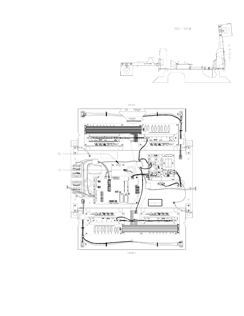
7.
Slip the washers onto the threaded end of the
standoffs (a). Screw the standoffs (b) into the
platform base. (Newer platforms already have two
fixed standoffs (b); in which case, the loose
washers and standoffs are not used). Connect the
RS-485 PCB to P8 of the CPU PCB (c). Secure the
PCB using the two 6-32 screws (d).
8.
Feed the DC cable up through the platform bushing (a). The DC cable is a 4-conductor gray cable with red, green,
white, and black wires terminated to a 5-position connector. It is part of the DC conduit assembly. Attach the DC cable
to P1 (b) of the RS-485 I/F PCB.
9.
Complete the wiring between the card system and DC junction box as shown in the Pump/Dispenser Installation Manual.
10. Secure the display panel in the upright position.
11.
Attach the bezel. Make sure the bezel is seated properly to insure a watertight seal.
12.
Attach and lock the front panel.
- 216S (18 pages)
- Atlas Fuel Systems Site Prep Manual (42 pages)
- Atlas Technician Programming Quick Ref (2 pages)
- ATC M05819K00X Kits (28 pages)
- Atlas Fuel Systems Owner Manual (80 pages)
- Gilbarco Global Pumping Unit Operation Manual (42 pages)
- 26 (7 pages)
- Atlas Valve Replacement Kits (10 pages)
- Atlas Fuel Systems Installation Manual (100 pages)
- 9120K (8 pages)
- 9820K (6 pages)
- Atlas Single Std. Inlet Centering Kit (8 pages)
- 8800 Atlas (1 page)
- 9120K Series Service Manual (40 pages)
- 9800A Atlas (6 pages)
- 9800 Atlas (14 pages)
- 9800 Atlas (20 pages)
- M08400 (6 pages)
- 9100 Series (8 pages)
- 9820K Series Installation (62 pages)
- 9853K (8 pages)
- 9216KTW (36 pages)
- Recommended Spare Atlas (14 pages)
- DEF Atlas (28 pages)
- 9820K Series (12 pages)
- 9800Q (1 page)
- Q Series (3 pages)
- 8753E (2 pages)
- 9152AXTW2 (1 page)
- 8800E (2 pages)
- 8800E (1 page)
- 9820Q Series (1 page)
- Atlas Start-up (230 pages)
- 2600A (12 pages)
- 2600A (2 pages)
- 9800Q Front Load Vapor (2 pages)
- 215A (1 page)
- 9800A (4 pages)
- 9820A (1 page)
- 2600A (3 pages)
- 216A (31 pages)
- 215A (2 pages)
- 9800Q Vapor (2 pages)
- Lamp Kit (2 pages)
- 9120Q Pulser (1 page)