Gasboy 580 Pulser User Manual
Instruction sheet for the model 580 pulser kit
023132 Rev 2144
INSTRUCTION SHEET FOR THE MODEL 580 PULSER KIT
This instruction sheet details the steps to install a pulser kit into an existing 580 pump. Be sure to follow all Warnings and
Safeguards as outlined in your 580 Installation/Operation/Parts manual. To install the new pulser kit, you must remove
the existing register and install the new pulser-enabled register and some additional parts. To make this process easier,
many of these parts are preassembled for you. This kit contains the following:
Register cable assembly
*048654
Register
*023089
Cable
Pulser/bracket assembly
*021788
Pulser
*015919
Pulser bracket
*025045
90° elbow
*014031
conduit
*066400
conduit union
*Components are pre-assembled to form assembly shown in bold print.
Junction Box and cover assembly
*003340
junction box
*003515
junction box cover
053910
screw
023074
junction box bracket
042290
cotter pin
052976
ground screw
067500
cupped washer
064874
ring terminal
023132
instruction sheet
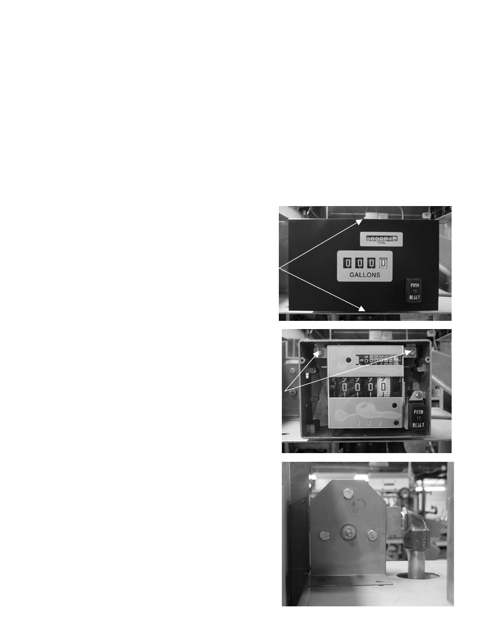
1.
Remove the dial mask from the register housing by removing
two screws on the top and bottom. See Figure 1. Keep these
screws; you will use them later.
2. Remove
the
PUSH TO RESET button and the spring, and set
aside.
3.
Remove two screws (Figure 2) that hold the register assembly
to the register housing. Slide register assembly to the left and
lift out.
4.
Install the new register assembly with pulser cable. Extend the
pulser cable outside the housing from the hole located on the
left side of the housing.
5.
Replace the reset button and the spring removed in Step 2, then
use the two screws to re-secure the dial mask to the register
housing.
6.
Install pulser/bracket assembly, running conduit through
provided hole in meter-register support plate (see Figure 3).
Secure to the support plate using two thread forming screws.
7.
Connect the pulser cable to the pulser shaft using the cotter pin.