Gasboy 9852K User Manual
Page 7
MDE-5151 Direct Pulse Out Option Installation Instructions for Atlas™ 9852K/9853K Pumps/Dispensers · March 2014
Page 7
Installing Direct Pulse Out Interface Board
6
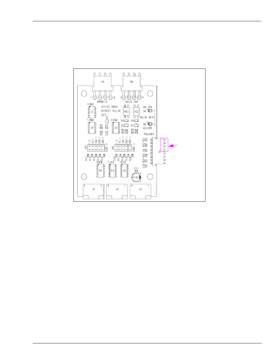
On the direct pulse out interface board, set the jumper to the desired pulse out rate (1, 10, 100,
250, or 500 pulses per gallon) for the side 1 on JP1. For dual pump, ensure to set the pulse out
rate for the side 2 on JP2.
Figure 2: Direct Pulse Out Interface Board
Single Pulser
Connects Here
7
Connect the pulser cable to P2 of the direct pulse out interface board. For single unit with only
one pulser, it connects to the first four pins of P2. Connect the pump handles cable to P4.
Locate the DC cable connector labeled J3 (4-conductor cable with brown, orange, yellow, and
gray wires) that is part of the DC conduit assembly. Attach the J3 cable connector to P3 of the
direct pulse out interface board.
8
Align the J3, J4, and J5 connectors on the direct pulse out interface board with P3, P4, and P5
of the CPU board. Gently press the two together. Be careful when pushing the direct pulse out
interface board directly toward the CPU board and avoid any side to side motion.
Note: The three connectors on each 9800 CPU board and direct pulse out interface board are
keyed to allow the boards to be connected properly.