Gasboy 9120K User Manual
Page 6
Installation of the 9120K Pulser Kit
Page 6
MDE-4618 9120K Pulser Installation Instructions • December 2006
4
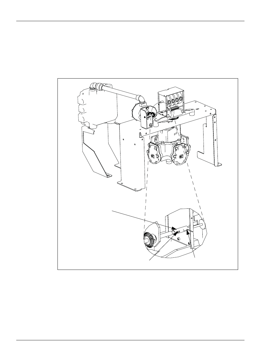
Align and install the Pulser, gears, bracket and conduit assembly to the platform, aligning the
shaft's pin to the slot in the coupling that was installed in the register's Totalizer shaft (see
). Use two ¼-20 X ½ Taptite screws to secure the Pulser, gears,
bracket and conduit assembly in place, while aligning the two existing holes in the platform.
Figure 2: Assembled View
Spirol Pin .078 X .437 (13)
Totalizer Coupling 9120K (12)
Spirol Pin .052 X .375 (9)
5
Open the junction box cover and connect wires appropriately inside the junction box. Retain
all screws.
Note: Direct Current (DC) wires must be on the left side of the divider plate inside the
junction box. For details, refer to MDE-4567 9120K and 9820K Series AST Pumps
Installation and Operation Manual.
6
Re-install the junction box cover with existing screws.
Note: All screws must be used to ensure an explosion-proof junction box.