Models 393-00x, 393al-00x, and 394al-00x – GAI-Tronics 300 Series RED ALERT Emergency Telephone Manual User Manual
Page 13
P
UB
.
42004-438K
300
S
ERIES
E
MERGENCY
T
ELEPHONE
M
ANUAL
P
AGE
11 of 45
f:\standard ioms - current release\42004 instr. manuals\42004-438k.doc
01/15
Models 393-00
x
, 393AL-00
x
, and 394AL-00
x
The mounting and wiring instructions are as follows:
1. Remove the four security screws from the front
panel and set the panel assembly aside, protecting
it from possible damage.
2. Position the enclosure on the mounting surface.
The enclosure provides four 0.28-inch mounting
holes in a 7.0
8.5-inch hole pattern. Secure the
enclosure to its mounting surface with four ¼-
inch diameter bolts of the appropriate length for
the surface.
N
OTE
: When using the GAI-Tronics Model
231-001 Pole Mounting Kit, follow the mounting
instructions provided in the kit.
3. For Model 393-00x only: Create a conduit access
hole using a Greenlee-type punch that is
equivalent in size to the conduit diameter.
Bottom entry is strongly recommended. Insert a
conduit fitting in the access hole.
4. Install conduit as required. Refer to conduit installation details on page 10.
N
OTE
: Use silicone sealant or equivalent around and inside all conduit entries.
5. Pull the telephone line through the conduit and into the enclosure. Connect the telephone line to the
customer-supplied telephone line surge suppressor (if applicable) and modular jack (USOC RJ11 or
CA11A) provided with the unit.
N
OTE
: The modular jack may be mounted inside the telephone. Telephone line connections directly
to TB1 are acceptable.
6. Allow the telephone a minimum of 35 seconds to initialize.
7. Using the “Setup” section of this manual,
Configure the hardware as required. Refer to the “Hardware Configuration” section on page 21
for details.
Adjust the audio levels, if necessary. Refer to Figure 23 for “Speaker Volume” and “Microphone
Sensitivity” potentiometer locations.
Perform the initial programming. Refer to the “Programming” section on page 30.
8. Verify operation by calling to and from another telephone.
9. Complete the installation by attaching the front panel assembly to the rear enclosure using the four
security screws, 10–12 in-lbs. of torque recommended.
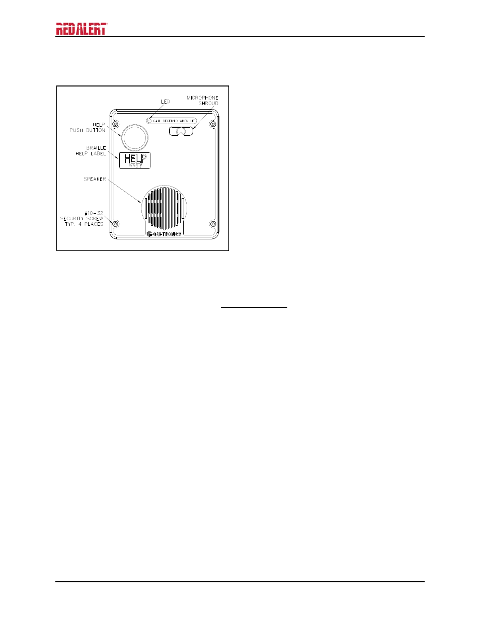
Figure 5. Model 393-00x Emergency Telephone
in a Non-Metallic Enclosure