Contact closure output connections – GAI-Tronics LE200-RM Rack-Mount Page/Party Line Extender User Manual
Page 33
Pub. 42004-392G
M
ODEL
LE200-RM
R
ACK
-M
OUNT
P
AGE
/P
ARTY
®
L
INE
E
XTENDER
P
AGE
31 of 56
e:\standard ioms - current release\42004 instr. manuals\42004-392g.doc
09/14
Table 29. TB8 and TB9
Terminal Designator
Description
TB8
Input 1 (+)
Input contact 1
TB8
Input 1 (−)
TB8
Input 2 (+)
Input contact 2
TB8
Input 2 (−)
TB8
Input 3 (+)
Input contact 3
TB8
Input 3 (−)
TB9
Input 4 (+)
Input contact 4
TB9
Input 4 (−)
TB9
Input 5 (+)
Input contact 5
TB9
Input 5 (−)
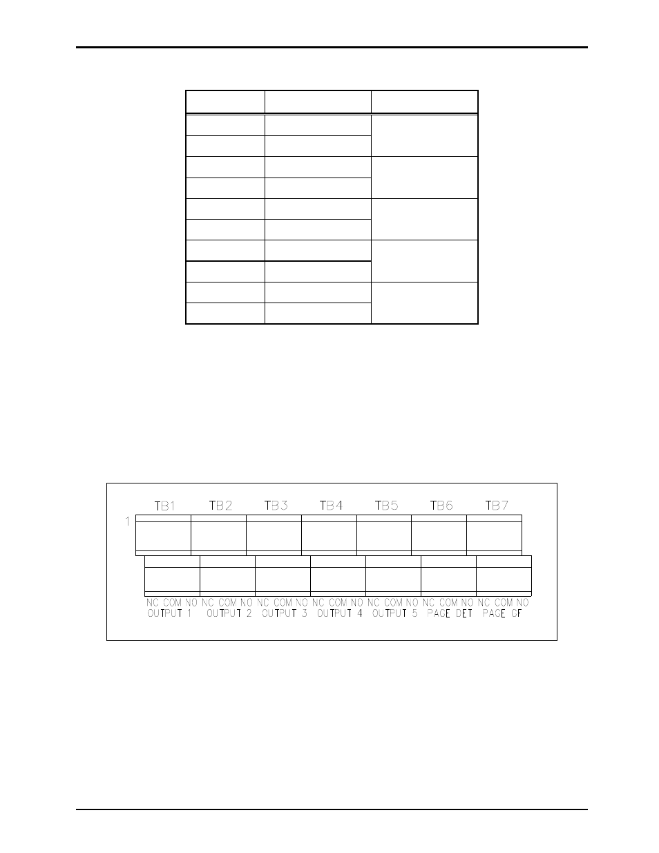
Contact Closure Output Connections
Seven relay outputs are provided. Each relay output provides two contact sets and each contact set
consists of normally open (NO), common (C) and normally closed (NC) contacts. Outputs 1–5 are
activated by inputs 1–5 on the remote Line Extender. Output 6 is activated when page line audio is
detected and output 7 is activated when a page line ground fault is detected. Terminals are provided on the
Model 12118-012 Kit for each relay contact and are labeled with the relay contact description next to the
terminal block TB1-7 as shown below.
Figure 16. Relay Output Terminals