Party line off-hook detection – GAI-Tronics LE200-RM Rack-Mount Page/Party Line Extender User Manual
Page 15
Pub. 42004-392G
M
ODEL
LE200-RM
R
ACK
-M
OUNT
P
AGE
/P
ARTY
®
L
INE
E
XTENDER
P
AGE
13 of 56
e:\standard ioms - current release\42004 instr. manuals\42004-392g.doc
09/14
Party Line Off-Hook Detection
The Model LE200-RM Line Extenders provide off-hook detection on the local Page/Party
®
system cable
for party lines 1 through 5. An off-hook condition means a handset station is in use. If multiple Line
Extenders are connected to the same Page/Party
®
system cable segment, only one off-hook detector can be
enabled. If connecting an LE200-RM to the same system cable segment as an ADVANCE Page/Party
Interface (PPI) card, disable the LE200-RM off-hook detection for party lines 1 and 2. The PPI card
contains off-hook detection for party lines 1 and 2.
Several shorting clips (P6–P15) are used to enable the off-hook detection feature on party line 1 through 5.
Two shorting clips are associated with each party line and must be set to the same position for proper
operation. The party lines 1–5 are configured independently. Refer to Figure 6 for the location of P6–P15
on the Main PCBA and Table 12 below for setting options.
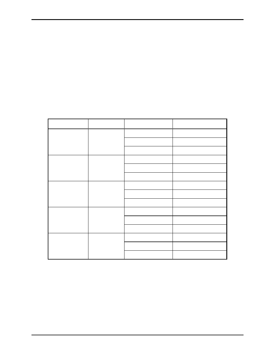
Table 12. Party Line Off-Hook Detection Setting on Main PCBA
Party Line
Headers
Shorting Clip
Off-Hook Detection
Party Line 1
P15, P14
Pins 1–2*
Disabled
Pins 2–3
Enabled
Removed Disabled
Party Line 2
P13, P12
Pins 1–2*
Disabled
Pins 2–3
Enabled
Removed Disabled
Party Line 3
P11, P10
Pins 1–2*
Disabled
Pins 2–3
Enabled
Removed Disabled
Party Line 4
P9, P8
Pins 1–2*
Disabled
Pins 2–3
Enabled
Removed Disabled
Party Line 5
P7, P6
Pins 1–2*
Disabled
Pins 2–3
Enabled
Removed Disabled
N
OTES
:
1. Changes to this parameter take effect without cycling power.
2. *Indicates default position.