Chapter 2 installation instructions – Foxconn 865M06-G-6EKS User Manual
Page 33
Chapter 2 Installation Instructions
25
865M06 Series User Manual
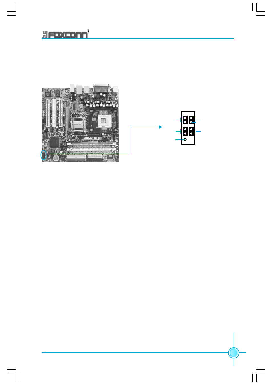
Front Panel Connector: CN35
This motherboard includes one connector for connecting the front panel switch
and LED indicators.
CN35
IDE LED Connector (HD-LED)
The connector connects to the case’s IDE indicator LED indicating the activity
status of hard disks.
Reset Switch (RESET)
Attach the connector to the Reset switch on the front panel of the case; the sys-
tem will restart when the switch is pressed.
Power LED Connector (PLED)
Attach the connector to the power LED on the front panel of the case. The Power
LED indicates the system’s status. When the system is in S0 status, the LED is
on. When the system is in S1 status, the LED is blink; When the system is in S3,
S4, S5 status, the LED is off.
Power Switch Connector (PWRSW)
Attach the connector to the power button of the case. Pushing this switch allows
the system to be turned on and off rather than using the power supply button.
NC
HD-LED
RESET
PLED
PWRSW
1
+
-
+
-