Initial alignment 4.6 – Flowserve VTP Wet Pit User Manual
Page 30
VERTICAL TURBINE PUMPS (VTPS) CENTRIFUGAL PUMPS ENGLISH 71569224
– 10-13
Page 30 of 76
flowserve.com
two line leads. To change direction of rotation on
a two-phase motor, interchange the leads of
either phase.
f) See impeller adjustment instructions (section 5.3
before bolting the pump and driver half of the
coupling together.
Initial Alignment
4.6
Thermal expansion
4.6.1
The pump and motor will normally
have to be aligned at ambient temperature and
should be corrected to allow for thermal expansion at
operating temperature. In pump installations
involving high liquid temperatures greater than 300°F,
the unit should be run at the actual operating
temperature, shut down and the alignment checked
immediately.
Preparation before alignment
4.6.2
To ensure proper alignment the following items are
very important.
a) All machined mating surfaces (such as the
mating flanges of pump and motor) must be
clean and free of burrs and nicks.
b) Exterior strain must not be transmitted to the
pump. The most common cause of trouble is
forcing the piping to mate with the pump. It is
recommended that flexible connectors be installed
in the piping adjacent to the pump.
c) All threads should be checked for damage and
repaired if necessary. Lubricate all threaded
connections with a suitable thread lubricant (an
anti-galling compound).
Alignment methods
4.6.3
Ensure pump and driver are isolated
electrically and the half couplings are disconnected.
The alignment MUST be checked.
Although the pump will have been aligned at the
factory it is most likely that this alignment will have
been disturbed during transportation or handling.
If necessary, align the motor to the pump, not the
pump to the motor.
Adding or removing shims between the
motor and the discharge head helps alignment in the
vertical direction. The motor assembly may also
have to be adjusted in the horizontal direction to line
up the driver and shaft centers. Alignment screws
are provided to lock the motor assembly in its final
aligned position.
See section 5.3.2.1 for final coupling alignment for
solid shaft.
Before bumping motor make sure that the
coupling halves are not touching and that the driver
can rotate freely without rotating the pump. Driver
half coupling must be in proper position so the
circular key will not come out.
Angular and parallel misalignment
4.6.4
Check the direction of pump rotation
before the coupling is fully connected. The power
supply to the driver to be connected only after the
final alignment is complete.
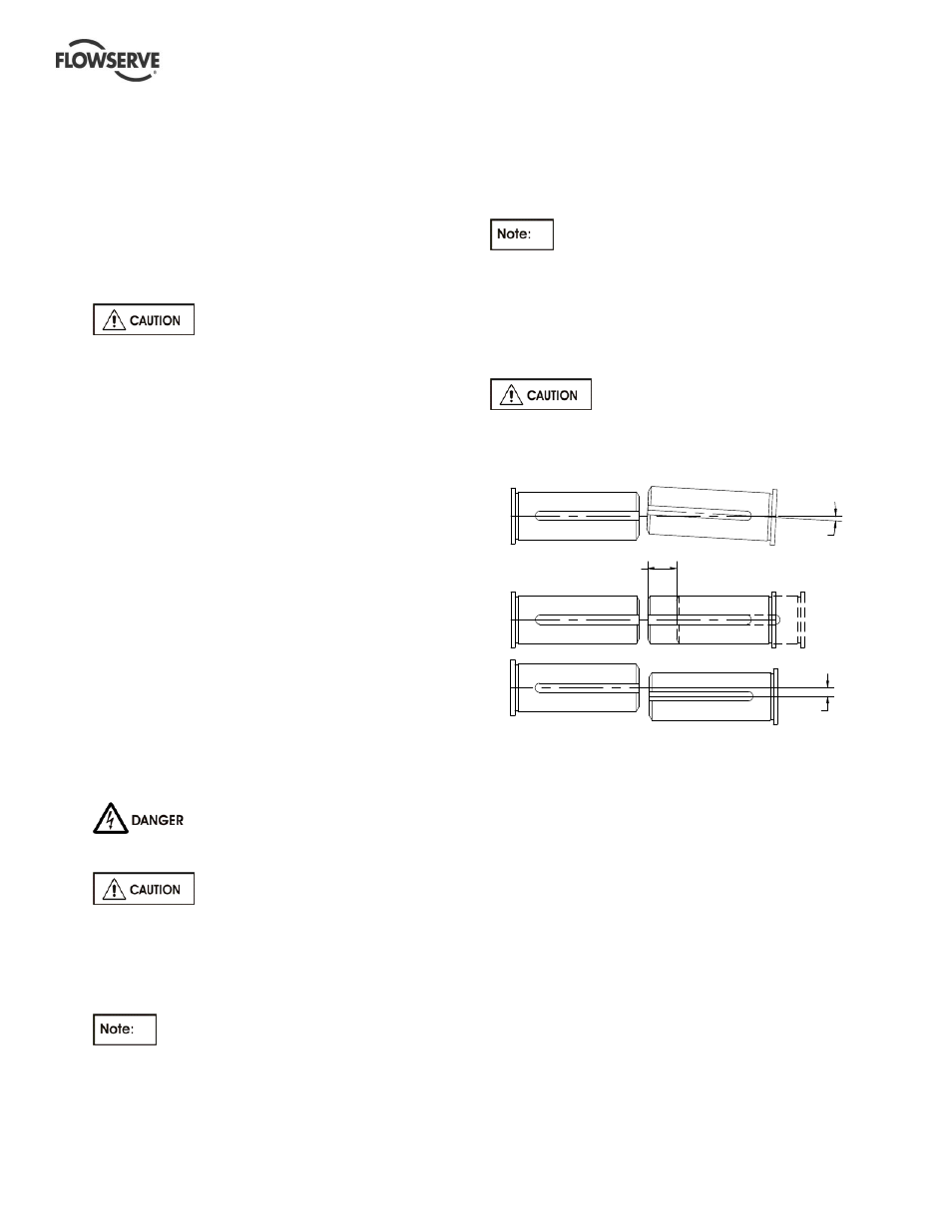
a) Angular Offset: The median lines of shaft
intersect halfway between the ends of the two
shafts.
b) Axial Offset: Another offset is the displacement
of one or both of the shafts. A typical example is
thermal expansion.
c) Parallel Offset: The median lines run parallel.
The maximum allowable parallel offset depends
on the size of coupling and is indicated in the
instruction manual of manufacturer of coupling.
For couplings with narrow flanges use a dial indicator
as shown in the detail to check both parallel and
angular alignment.
Parallel offset
Angular offset
Axial offset
a)
b)
c)