Flowserve VTP Wet Pit User Manual
Page 22
VERTICAL TURBINE PUMPS (VTPS) CENTRIFUGAL PUMPS ENGLISH 71569224
– 10-13
Page 22 of 76
flowserve.com
provision of correct foundation and installation may
lead to failure of the pump and, as such, would be
outside the terms of the warranty.
The foundation must consist of material that will afford
rigid support to the discharge head and will absorb
expected stresses that may be encountered in service.
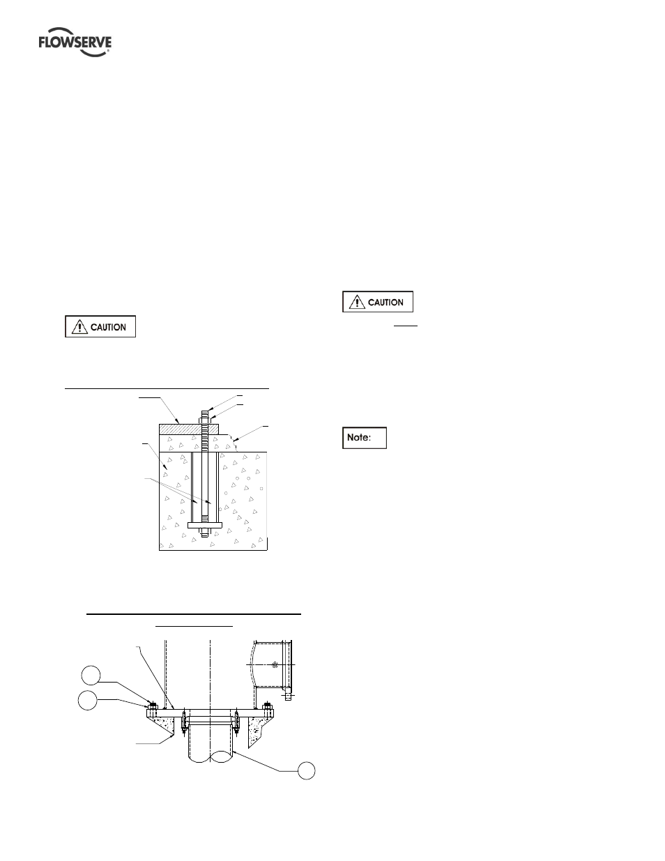
Concrete foundations should have anchor bolts
installed in sleeves that allow alignment and have
holes in the mounting plate as illustrated in the detail
below. Sleeve should be filled with non-bonding
moldable material after sleeve is set in place.
When a suction barrel is supplied as in the case of the
type "TF" discharge head, the suction vessel must
provide permanent, rigid support for the pump and
motor.
All foundation / anchor bolt
recommendations should be verified by prevailing
industry standards.
Detail of a typical foundation bolt, grouted.
Leveling of pumps mounted on the
4.3.1
discharge head flange
Example of a typical discharge head with the
mounting flange
Some wet pit pumps are installed directly by using
the flange that comes as an integral part of the
discharge head. The pump is lowered into the pit
and aligned with the anchor bolts [372].
The mounting flange is shimmed to achieve required
level by using a precision machinist’s level. The
pump is to be leveled to within 0.16 mm/m
(0.002 in./ft). The data to be recorded for future
reference. Anchor bolt nuts [373] are tightened
sufficient enough to hold down the pump in place.
Grout is poured and allowed to set for at least 72~80
hours (cure as required) before any further work is
done on the pump.
If leveling nuts are used to level the
base, they must be backed off as far as possible prior
to grouting.
Always shim near foundation bolts and then back off
the leveling nuts. Now tighten the foundation bolts. If
done otherwise there is a risk of significantly lowering
the structural natural frequency that could result in
separation of the base from the grout.
Directly mounted pumps are not user
friendly for service. Re-installation of these pumps
requires re-leveling and re-grouting.
Leveling of pumps mounted on a
4.3.2
soleplate and the soleplate is grouted
Some pumps are mounted on a separate plate
known as soleplate [23]. In such cases, the level
shall be set with a master level or a precision
machinist’s level. The mounting surface needs to be
leveled to within 0.16 mm/m (0.002 in./ft).
The level should not exceed 0.125 mm (0.005 in.)
elevation difference taken on any two points on the
individual soleplate. Accurate shimming and grouting
of the soleplate is very important. Record the leveling
data for future reference. Grout the soleplate and
allow to set at least 72~80 hours (cure as required)
before the pump is lowered into the pit. Align the
discharge head boltholes with the anchor bolts [372].
Check and adjust the pump level to within
0.16 mm/m (0.002 in./ft) with respect to the soleplate
and torque the nuts [373] to the required level.
DISCHARGE
HEAD FLANGE
CONCRETE
372
373
101
MOUNTING PLATE
ANCHOR BOLT
GROUT
NUT
NON-BONDING
MOLDABLE MATERIAL
FOUNDATION