Troubleshooting – DC Power Technologies FS3 Version 3 - Technical Hardware Manual User Manual
Page 41
Page | 40
11. Troubleshooting
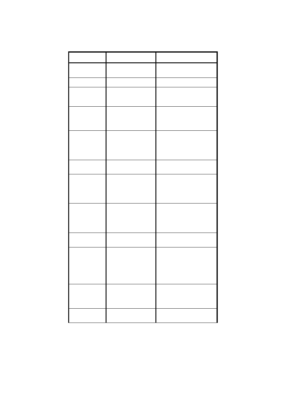
Problem
Possible Cause
Remedy
Main Switch
Alarm
Front panel switch in
the STOP position
Charge will start when the
switch is set to START
Inlet Filter Alarm
Air inlet filter blocked
Clean the filter
Low Mains
Alarm
AC mains supply is low
or charger modules
may be overloaded
Check configuration of the
charger suits the application
Non-Urgent
Rectifier Fail
Alarm
charger module not
providing output, there
is capacity to charge at
a reduced rate
Replace the faulty charger
module(s)
Urgent Rectifier
Fail Alarm
Faulty charger
modules are affecting
the ability of the
charger to charge the
battery
Replace the faulty charger
module(s)
Rectifier Fan
Fail
Faulty charger module
fan
Replace charger module
Rectifier Over
Temperature
Charger module is
overheating
Check air inlet filter is not
blocked, check the charger is
installed without any
obstructions to air inlet and
outlet
Configuration
Error
Charger cannot
provide the target
output current
Check the controller
configuration matches the
quantity of Charger modules
installed, add charger
modules if necessary
Output Fuse
Blown output fuse
Check battery polarity,
replace blown fuse
No Output
Current
Battery unplugged
during charge.
Charge profile allows
current to fall below
0.7A.
Ensure battery has not been
unplugged before charge
completion.
Check that the charge profile
is appropriate for the battery
type.
Monitor ADC
Fail
Faulty MPC35
controller module
Replace the MPC35
controller module ensuring
the replacement is correctly
configured
Low Output
Current
Only one battery cable
connected (FS9).
Ensure two battery cables
are connected to the FS9.