Fs5, fs9 – DC Power Technologies FS3 Version 3 - Technical Hardware Manual User Manual
Page 10
Page | 9
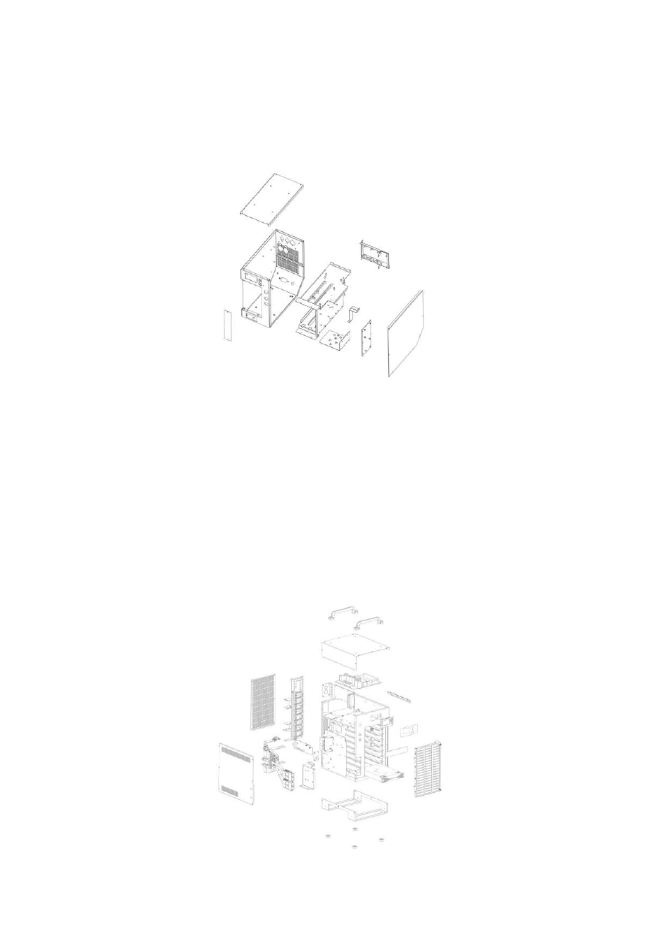
FS3
The front of the FS3 housing takes up to three charger modules in
a vertical, side-by-side orientation. Top and side covers allow
access to the main serviceable internal areas of the FS3,
removable in that order.
FS5, FS9
These models share a common frame and external housing, the 5/9
designation is determined by internal hardware and circuitry with
the FS5 and FS9 supporting an operating maximum of five and nine
modules respectively.
Access to the module bays is via the air filter assembly on the front
face of the housing. Installed in the module bays, each charger
module is supported in a horizontal orientation by the internal
chassis.
The FS5 and some FS9 models require a single rather than double
DC output connectors. These models are fitted with a steel blanking
plate in place of the DC connector location.