Charger module led combination states, Module installation and removal, Orientation for installation – DC Power Technologies FS3 Version 3 - Technical Hardware Manual User Manual
Page 20: Module removal
Page | 19
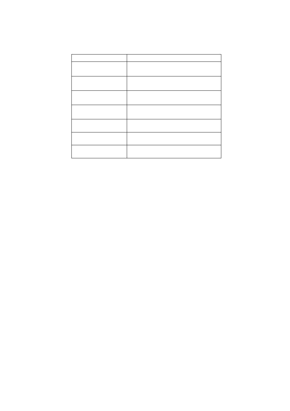
Charger Module LED Combination States:
Charger State
LED State
AC Power OFF
Battery Disconnected
No LEDs illuminated
AC Power ON
Battery Disconnected
No LEDs illuminated
AC Power ON
Battery Connected
Red LEDs illuminated
AC Power OFF
Battery Connected
Red LEDs illuminated
Charge Cycle Stage:
Constant Current
Green & amber LEDs illuminated
Charge Cycle Stage:
Constant Voltage
Green LEDs illuminated
Charge complete
Battery connected
Red LEDs illuminated
NOTE: Charger alarm indicators are reset if the battery is
disconnected.
Module Installation and Removal
Ensure the charger is removed from AC supply before
installing or removing modules.
Modules are installed through the front of the charger housing. The
air filter assembly must first be removed to gain access to the
module bays.
Only a small amount of force is required to have the module
connect with the charger backplane. Once the module is fully
inserted, engage the locking tabs at each side of the module front
panel. A module removal tool is available combining the module
locking and removal requirements into one tool. A small pair of
needle-nosed pliers is a good alternative.
Orientation for Installation
It is important the module orientation be correct before installing a
module.
FS5, FS9
The module must be oriented horizontally with the front panel type
identification up-right and readable.
FS3
The modules must be installed vertically so that the rear blue
connector is at the top.
Module Removal
To remove a module, first unlock the green locking tabs and, using
either the module removal tool or needle-nosed pliers on the
module grille, draw the module forward from the housing.