Controller replacement, Figure 24: display controller – Daktronics KE-1010-7.6-RG User Manual
Page 30
Controller Replacement
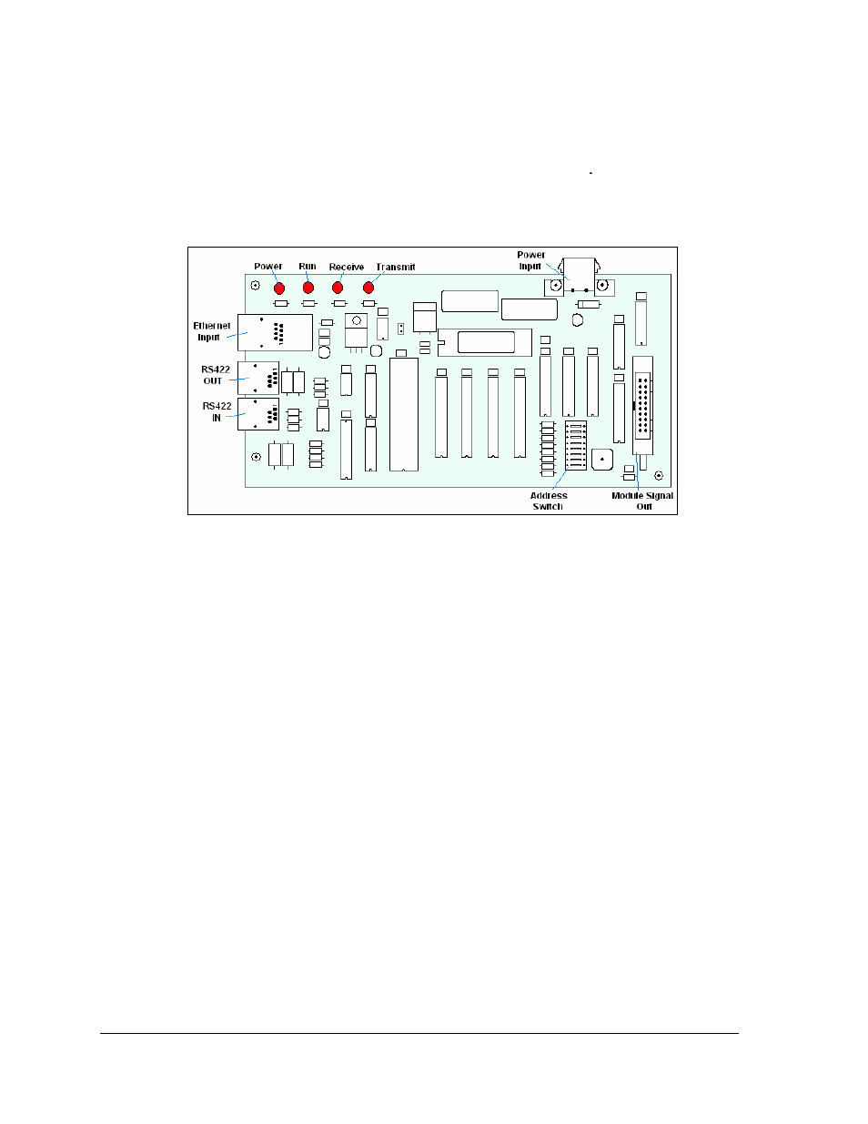
The controller is mounted inside the master display on the back of the cabinet (Figure 24). It
is typically located behind the second module from the right end. The display controller
receives information from the ticker input, interprets it, and activates the corresponding
LEDs. The controller has a set of eight switches, the first four of which are used to set the
hardware address using standard binary code. Refer to the following section for instructions
on setting the address. Display controllers are found only in master displays.
Figure 24: Display Controller
To replace a controller:
1. Disconnect the main supply power to the master section.
2. Remove the face panel per Section 6.2.
3. Remove the two LED modules on the right end of the master section.
4. Remove all power and signal cables to the controller, noting their connections.
(Signal to the controller may also be connected from the back of the display.)
5. The controller is attached to the inside of the display with four #6-32 hex-head
screws. Remove the attaching screws and carefully lift the controller from the
display.
6. Follow the previous steps in reverse order to attach a new controller. Refer to the
appropriate display Schematic for wiring information.
Note: Be sure to set the new controller’s address to the same settings as the one it is
replacing. Refer to the following information.
Parts Replacement
24