Section to section connections, Master to master connections, Figure 14: shift board – Daktronics KE-1010-7.6-RG User Manual
Page 18: Figure 15: master to echo connection, 3 master to master connections
4.2 Section to Section Connections
The signal between the master and echo sections is connected using 20-pin ribbon cables
between the shift board and the last module of the previous section (Figure 15). Follow these
steps to connect display sections.
Signal Installation
12
1. Carefully hang the echo section(s) as described in
Section 2.2. Do not yet slide the sections together.
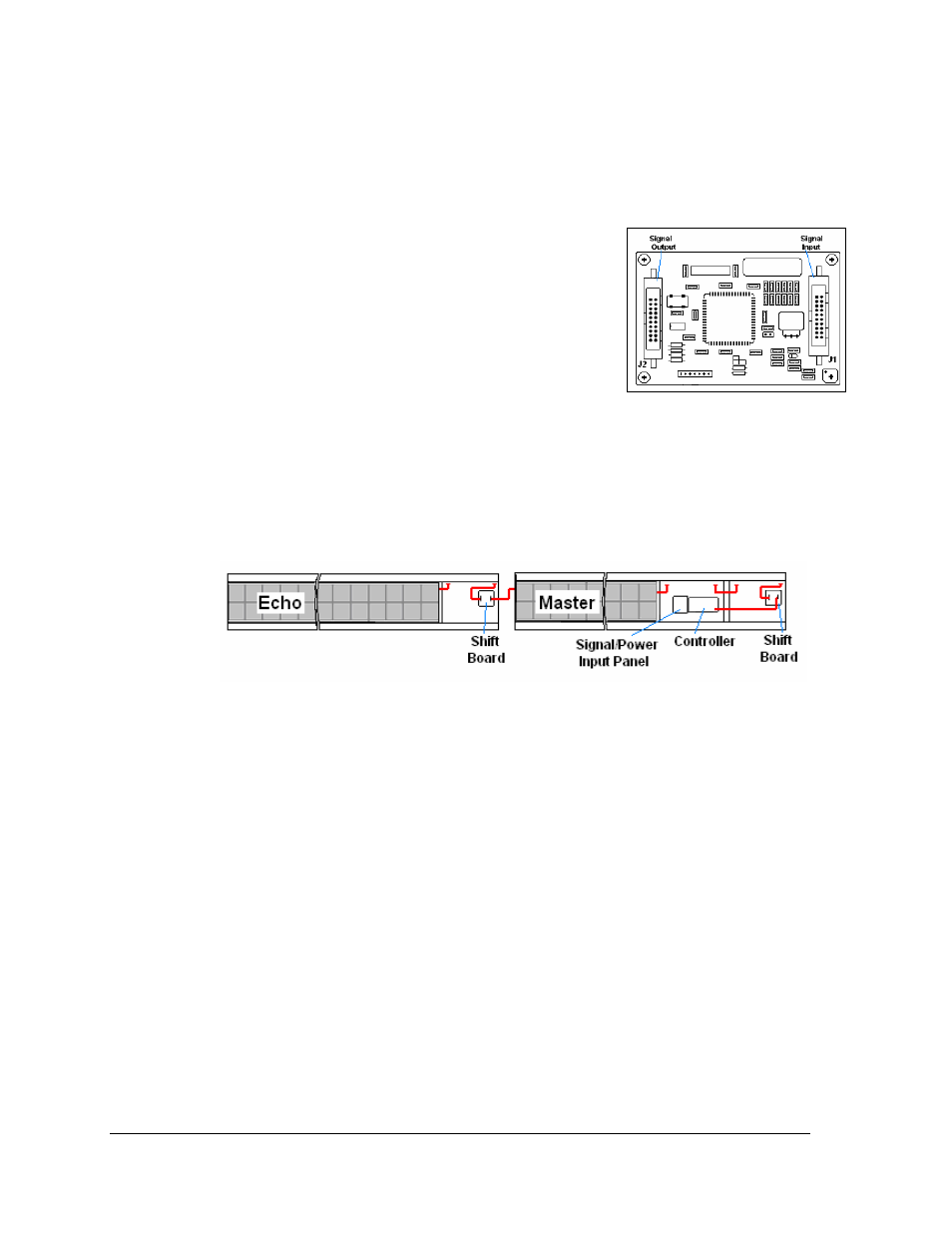
2. A ribbon cable should already be plugged into the
“Signal In” jack on the shift board (Figure 14) of the first
echo section. If it isn’t, do so at this time.
3. Plug one end of the ribbon cable into the “Out” jack on
the back of module A101 (the left end module) of the
master section.
4. If an echo section is present, plug P42/P43 of the echo
section into J42/J43 of the master section to complete
the interconnection of power. Repeat this for additional sections. Note: Total display
length cannot exceed 20 feet per power cord.
Figure 14: Shift Board
5. The connection for a master to one echo is shown in Figure 15. Repeat steps 1 though
3 to connect and hang each consecutive echo ticker. All other internal wiring
between modules has been done by Daktronics.
Figure 15: Master to Echo Connection
4.3 Master to Master Connections
In some cases, more than one master display is used instead of the master-echo
configuration. In this case, signal can be transmitted between master displays using a flipped
6-conductor RJ11 cable running RS-422. To connect multiple master displays:
1. Signal into the first display can be either RS-422 or Ethernet.
2. Connection between displays will always be RS-422. Connect from RS-422 OUT on
the first display to RS-422 IN on the second display (Figure 16).
3. Master displays connected in this way will need to have different addresses set on
each controller.