Power supply replacement, Shift card replacement, Figure 22: power supply wiring – Daktronics KE-1010-7.6-RG User Manual
Page 29: Figure 23: shift board
Power Supply Replacement
Power to the LED modules is provided by +5 VDC power supplies. To remove a power
supply:
1. Disconnect the main supply power to the section requiring service.
2. Remove the face panel per Section 6.2.
3. Remove the LED module in front of the failed power supply. Refer to the
appropriate Component Layout Drawing for the location of the power supplies.
4. The plate is secured to the back sheet by two (2) #6 nuts. Remove the #6 nuts to
remove the plate with the power supply. Lift the power supply and plate out of the
display.
5. Each power supply is attached to a
mounting plate by two (2) M4x8MM
metric screws. Using a #1 Philips
screwdriver, remove the screws to free
the power supply.
Figure 22: Power Supply Wiring
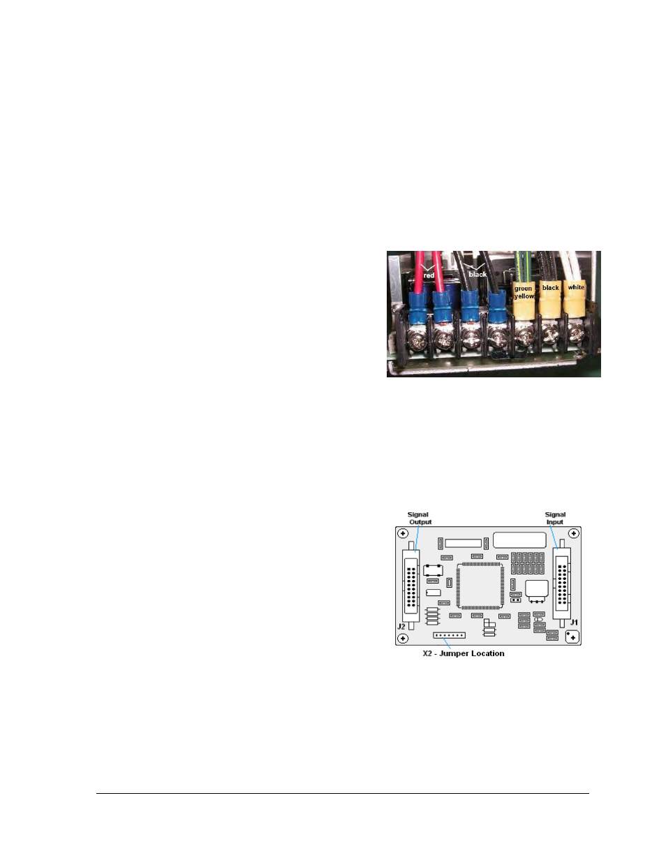
6. Disconnect all power supply wires,
noting their connections (Figure 22). The
power supply is now ready for
replacement.
7. Follow the previous steps in reverse
order to reattach the new power supply.
Shift Card Replacement
The shift cards are used to relay signal from the controller to the modules or from the last
module of the previous section to the LED modules in the next section. One shift card is
located in the right end of each KE-1010 section (both master and echo). To replace a shift
card:
1. Disconnect the main supply power to the
section requiring service.
Parts Replacement
23
2. Remove the face panel per Section 6.2.
3. Remove the last module in the right end
of the selected ticker section.
4. Remove signal cables from the shift card,
noting the correct connections (Figure
23
).
5. The card is attached to the inside of the
display with four #6-32 hex-head screws.
Remove the attaching screws and
carefully lift the card from the display.
6. If a jumper is present, make sure it is in
the same location as the board being replaced.
Figure 23: Shift Board
7. Follow the previous steps in reverse order to attach a new shift card. Refer to the
appropriate display Schematics for wiring information.