4descriptionsoftheports, 1descriptionofcomport, 2productionmethodsofethernetrj45cable – CREATOR DIG Series Full Digital conference system User Manual
Page 13: 5descriptionsofpanelbuttons, 1thelcddisplay
CREATOR CHINA
2012-11 WWW.CREATOR1997.COM
6
User's Manual of DIG series Full Digital conference
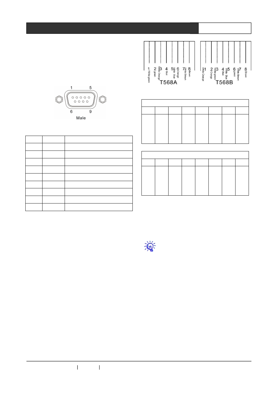
2.1.4 Descriptions of the ports
2.1.4.1 Description of COM port
Full digital conference system can use a
variety of control systems via RS-232 serial
interface.
COM port pin is described as follows:
Pin
Signal
Description
1
-
Null
2
TXD
sending data
3
RXD
Receiving data
4
-
Null
5
GND
Signal ground
6
-
Null
7
-
Null
8
-
Null
9
-
Null
2.1.4.2
Production
methods
of
ETHERNET RJ45 cable
The system uses shield five line as the wire,
and install RJ45connector (commonly known as
crystal head) at the CAT5 ends, and connect the
equipment with straight line access network. The
standard connection of twisted pair is not arbitrary,
it is to ensure the symmetry of cable connector
layout, thus to offset the interference between the
cables in connector. Super five lines generally
have four pairs of twisted thin line, which are
marked with different colors.
Twisted pair there are two kinds of
connection: EIA / TIA 568B standard and EIA / TIA
568A standard
T568A
linear order
1
2
3
4
5
6
7
8
whi
te
gre
en
gre
en
Wh
ite
ora
nge
blu
e
whi
te
blu
e
ora
nge
whi
te
bro
wn
Bro
wn
T568B linear order
1
2
3
4
5
6
7
8
whi
te
ora
nge
ora
nge
whi
te
gre
en
blu
e
whi
te
blu
e
gre
en
whi
te
bro
wn
Bro
wn
Direct line: both ends are connected by
T568B line sequential standard.
Cross-line: one end is connected by T568A
line sequential standard, the other is connected
by T568B line sequential standard.
When connected to the network router, it
uses
the
straight
line
connection.
When
connected to a PC computer control, it uses
crossover cable connection.
2.1.5 Descriptions of panel buttons
2.1.5.1 The LCD display
The LCD display is in steady state