3 installation – Comtech EF Data CMR-5910 Manual User Manual
Page 22
Digicast Media Router Serial IP (SIP): CMR-5910 (MG-SIP) & CMR-5920 (MR-SIP)
Revision A
Installation & Initial Configuration MN/MDRTRIPDC.IOM
• Contact
Comtech EF Data Customer Support if the shipment is:
! Incomplete
! Physically damaged
! Inoperable
2.3 Installation
The MG-SIP and MR-SIP are designed for ease of installation and configuration.
Once the device has been removed from the packing container, follow these
instructions:
Step
Procedure
1
Place the device on a flat surface with free-air flow where the LEDs can be
clearly observed with unrestricted access to the rear panel of the device.
2
Connect the DC power connection to the connection labeled PWR on the back
of the device and tighten the restraining nut to ensure secure operation.
3
Connect an RJ-45 Ethernet cable (patch cord) to the port labeled ETHERNET.
This cable should be connected to an Ethernet concentrator (hub) or switch.
4
Connect a terminal cable (supplied) to the port labeled TERM. This cable
should be connected to a PC’s serial port (DB-9) to initially configure the IS.
5
Connect the AC power cord between a standard wall outlet and the power
supply. The blue LED will illuminate.
6
IMPORTANT
The port labeled REDUN is currently not supported.
It is recommended that the RS-422/RS-530 cable NOT be
connected until after the device has been completely configured.
7
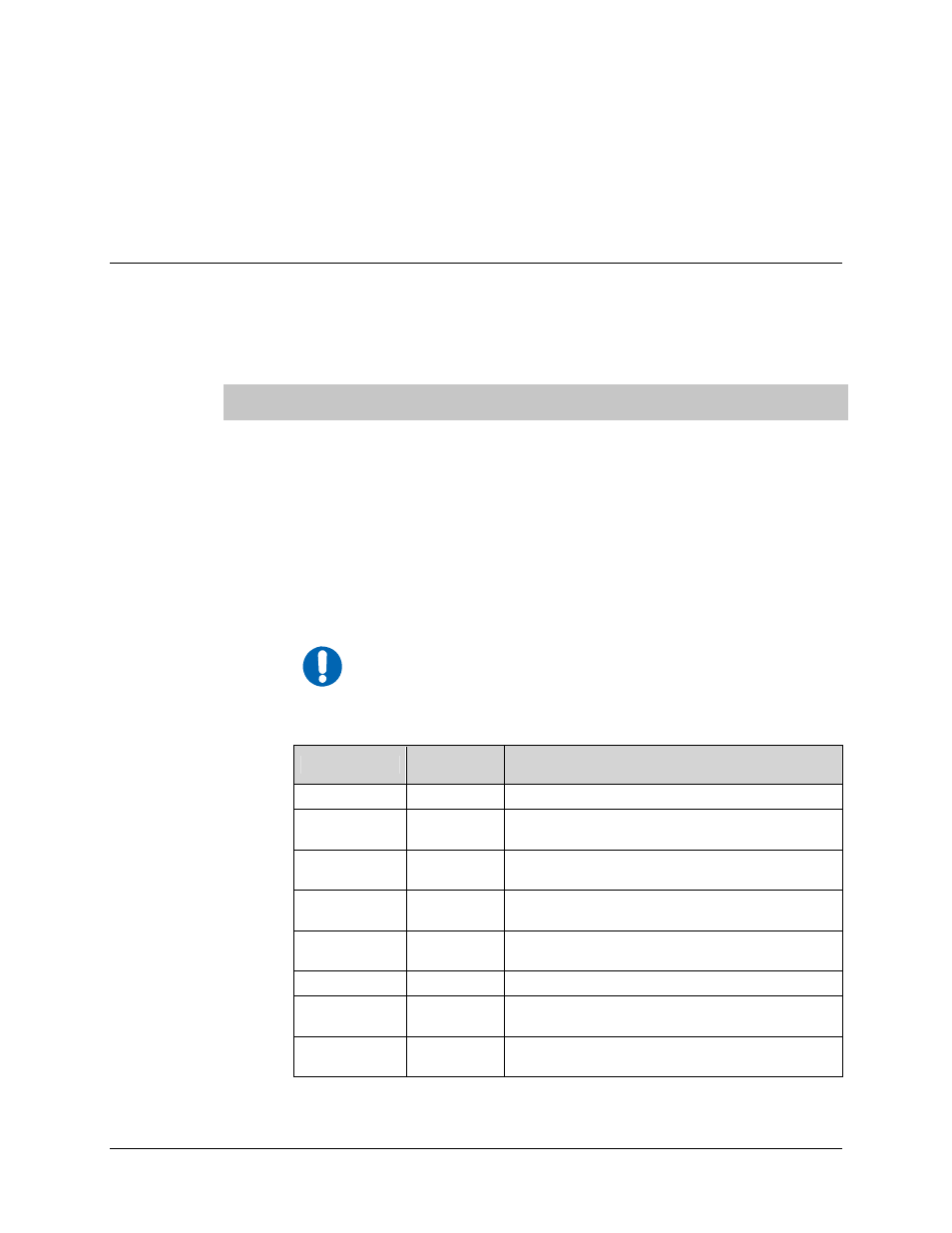
Upon startup, the LEDs on the device front panel become operational as follows:
LED
Function
Label
Description
Blue
PWR
LED illuminates if power is properly applied
Green
RED
LED will not illuminate – reserved for future
redundancy functionality
Red
ALARM
LED may illuminate since the device is not yet
configured
Green
SYNC
LED illuminates if traffic is being routed to the
RS-422 interface
Amber
E-COL
LED flashes if there are collisions on the
Ethernet switch
Green
E-RX
LED flashes if there is activity on the switch
Green
E-TX
LED flashes if the device is transmitting data to
the Ethernet
Green
E-LINK
LED illuminates if the Ethernet connection to
the Hub/Switch is operational
2-2