3 connect power supply systems, 1 power supply system description, Connect power supply systems -2 – Cadac F-Type User Manual
Page 10: 416 &rqqhfw#3rzhu#vxsso\#v\vwhpv
1-2
Connecting the mixer systems
F-Type
Revision F2005-2
416
&RQQHFW#3RZHU#VXSSO\#V\VWHPV
41614
3RZHU#VXSSO\#V\VWHP#GHVFULSWLRQ
Cadac consoles are designed to allow the use of two independent power supply sys-
tems in a redundant configuration – “main” and “backup”. Both sets of power supply
units are used to power the console system so that under normal conditions, the
‘load’ is shared between the “main” and “backup” PSU’s. If a fault occurs in one of the
power units (causing it to ‘shut-down’), the remaining power unit will power the con-
sole.
For smaller B-Type consoles (consuming no more than 44A), it is possible to use the
8400 PSU. See
1.3.7 8400 switch-mode power supply unit
.
One ±18V PSU and one +13V/+48V PSU is referred to as a “PSU System”.
Designate one pair of power supply units as “SYSTEM 1" and the other as “SYSTEM
2". PSU System 1 .and PSU System 2 should be connected to the same
phase and
on the same ‘spur’, wherever possible. In situations where it is necessary to provide
a separate ‘feed’ to each PSU system pair, make sure that the cable lengths are the
same. This is to minimize any induced a.c. power input noise by ensuring that the
“EARTH IMPEDANCE” is the same for both PSU systems.
/
1
(
/
1
(
/
1
(
/
1
(
-
-
-
-
$5($#%5$1&+#3$1(/
$5($#%5$1&+#3$1(/
$5($#%5$1&+#3$1(/
*1'#%$5
*1'#%$5
1#/
0$,1#*5281'#5()(5(1&(#($57+#(/(&752'(#6<67(0
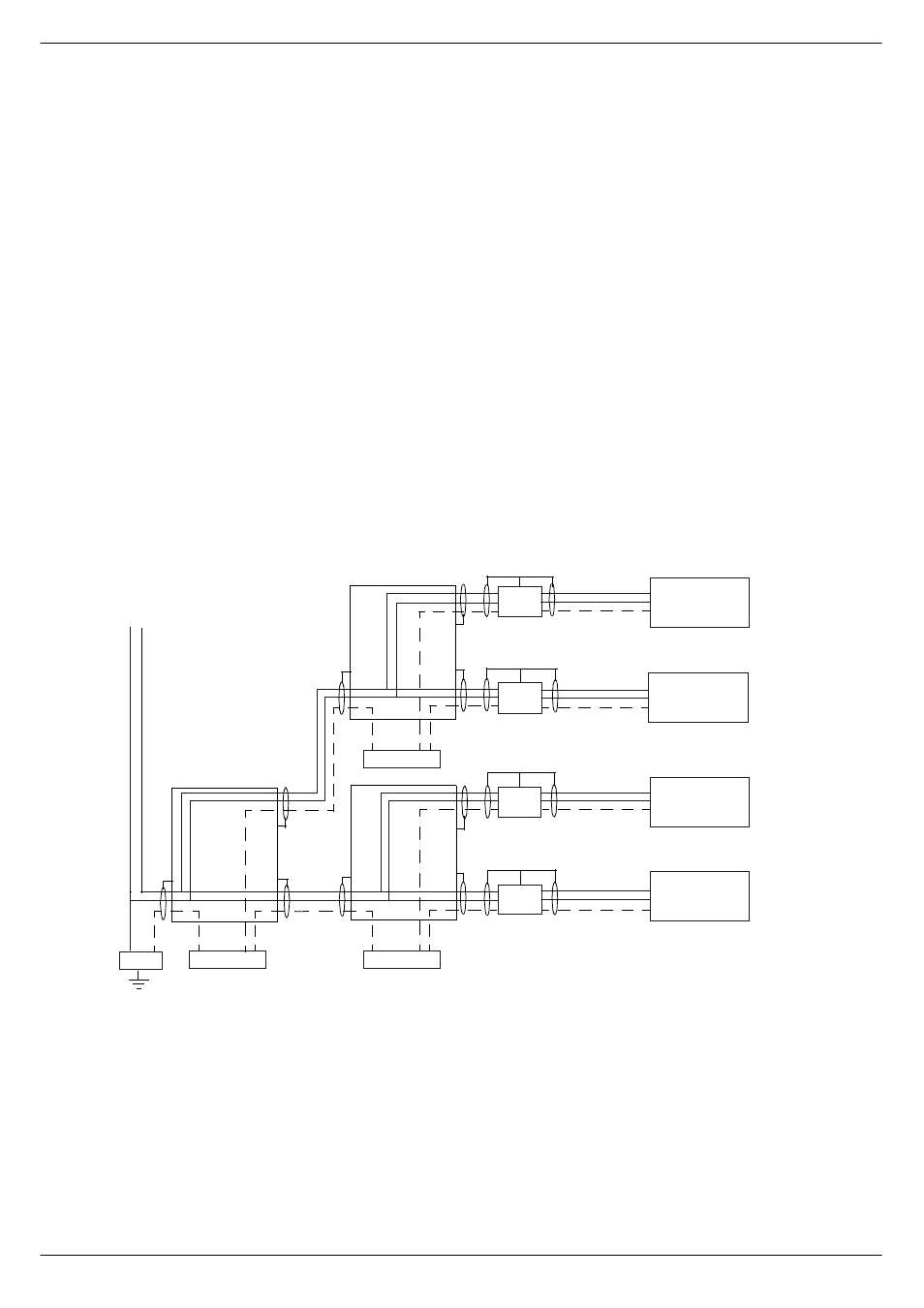
FIG 1-2. AC mains grounding diagram (single phase 200-240V)
368#4$
368#4%
368#5$
368#5%