1xt-1xc_willow_led, rev1, Fixture installation guide – Besa Lighting Willow (Mini Pendants 12V) User Manual
Page 3
6695 Taylor Rd. Blacklick, OH 43004
www.besalighting.com
FIXTURE INSTALLATION GUIDE
Model Willow LED (1 Light Low Voltage LED Dome Canopy)
1XT-1XC_Willow_LED, Rev.1 5-13
IMPORTANT: This 3W LED Pendant requires a constant current driver for proper operation.
Incorrect polarity from the driver will result in the LEDs not illuminating.
CAUTION: Turn off power to electrical box before installing
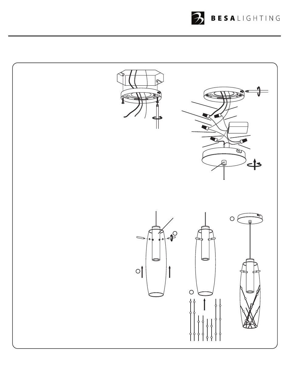
1. Carefully unpack parts. Secure
Mounting Plate (A) to the Outlet Box
with Mounting Screws (B). Pull House
Supply wires and House Ground
through Mounting Plate Hole.
2. Connect the LED Driver Leads to the
House Supply Wires with Wire Nut
Connectors (C) as shown: Brown Driver
Lead to Black House Supply Wire and Blue
Driver Lead to White House Supply Wire.
Then connect the LED Driver Leads to the Pendant
Cord Leads with Wire Nut Connectors (D) as shown:
Red Driver Lead to Clear Inner Lead and Black Driver
Lead to Braided Outer Lead. Connect the House Ground Wire
to the Canopy Ground Wire with Wire Nut Connector (E).
Carefully push the wires and wire nuts back into the Outlet Box.
3. Align Canopy Slot Opening (F) with Mounting Plate Screw (G), then
install Canopy (H) onto Mounting Plate (A) by rotating the Canopy
Clock-wise. Then tighten the Mounting Plate Screws (G) to secure Canopy in place.
4. Adjust the height of pendant by loosening Set Screw, using the provided Allen Wrench, and lowering or raising
the pendant to desired height. Once length of pendant at desired height, tighten Set Screw using the provided
Allen Wrench to secure pendant in place.
Black Supply
Lead
White Supply Lead
Blue Driver Lead
Red Driver
Lead
Brown Driver
Lead
Clear Inner
Lead
Allen Head Set Screw
Braided Outer
Lead
Black Driver
Lead
Lightsource
Canopy Ground
Wire
House Ground
Wire
B
G
F
H
D
D
C
C
E
A
A
All electrical connections and the installation of this fixture must be in agreement with local codes,
ordinances or the NEC (National Electric Code) or CEC (Canadian Electrical Code).
Do not connect this fixture to an electrical system that does not provide a means for equipment grounding.
7
8
5
6
GLASS INSTALLATION:
5. Install Glass by sliding the Glass over the
Lightsource and aligning the holes of the
Glass to the holes of the Lightsource.
6. Install Posts through the holes in the Glass and
thread into the Lightsource to secure the Glass.
7. With provided Crystal-rods, install each by
sliding one by one into the bottom opening of
the Glass. Adjust each Crystal-rod accordingly
to meet desired look.
NOTE: Crystal-rods are accents included with
the fixture, but customizable accents are optional.
8. Restore power.
NOTE:
Glass Shade is for
instructional purposes.
Actual Glass Shade may
vary in size and shape.