Besa Lighting Groove (Vanity) User Manual
Fixture installation guide
6695 Taylor Rd. Blacklick, OH 43004
www.besalighting.com
Use With
these Models:
• SR Groove
(6773MR)
All electrical connections and the installation of this fixture must be in agreement with local codes,
ordinances or the NEC (National Electric Code) or CEC (Canadian Electrical Code).
Do not connect this fixture to an electrical system that does not provide a means for equipment grounding.
FIXTURE INSTALLATION GUIDE
Models SR/SW Series (Two, Three, and Four Light Vanity 120V)
SR.96 Bath, Rev.1 8-12
Caution: Turn off power to electrical box before installing
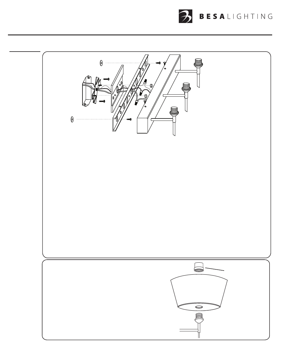
1. Carefully unpack and remove Hex Head Screws(J), releasing Mounting Plate(A) from Canopy(H).
Important: Before proceeding, confirm your mounting scenario. For a Downlighting scenario, the
Socketholders(M) must be inverted (see Diagram A). For a low-profile look, the Decorative Finial
may be replaced with a Decorative Cap (see Diagram B).
2. If installing to an Outlex Box, extend supply wiring through the Crossbar(C) and secure to the
Outlet Box with machine screws(B) provided. For offset purposes where outlet box is to be
off-center, use additional wood screws and wall anchors for support in lieu of the crossbar. If an
Outlet Box is not present, eliminate the use of the Crossbar and Box Cover(D) and proceed to
step #3. A romex or BX clamp is advised when using flexible cable.
3. Place the Box Cover(D) and Mounting Plate(A) over Crossbar for placement of Wall Anchors(E).
After installing Anchors, reposition the Box Cover and Mounting Plate and secure with the
Cap Nuts(F). Then secure the ends of the Mounting Plate by threading the Wood Screws(G)
into the Wall Anchors.
4. Attach the Fixture Ground wire to the supply ground and secure with Wire Nut connector (K).
5. Connect the fixture conductors to the supply conductors with wire nut connectors (L) as shown:
White fixture wire to white supply wire and black fixture wire to black supply wire.
Carefully push wires and wire nuts back into outlet box.
6. Place the fixture Canopy (H) over the Mounting Plate so that the threaded openings in the
Mounting Plate align with the two holes in Canopy. Secure with two Hex Head Screws.
A
C
D
E
J
H
B
F
G
K
L
M
NOTE: Glass shown is for
instructional purposes. Actual
Glass may vary in shape or size
7. Install the Glass Shade per diagram.
8. Install bulb provided (40W Max., Type G9)
and restore power
CHECK RING
NOTE: 3-Light fixture shown is for
instructional purposes, actual
luminaire may be 2-Light or 4-Light
as well. Box Cover shape will vary
by Model Number.
- Palla 5 (Vanity) Tay Tay (Vanity) Divi (Vanity) Mia (Vanity) Peri (Vanity) Hoppi (Vanity) Lasso (Vanity) Domi (Vanity) Brella (Vanity) Canto 5 (Vanity) Kani (Vanity) Kona (Vanity) Sabrina (Vanity) Nico 4 (Vanity) Pahu 4 (Vanity) Focus (Vanity) Copa 3 (Vanity) Copa 3 (Mini Sconces) Groove (Mini Sconces) Jodi (Vanity) Palla 5 (Mini Sconces) Tay Tay (Mini Sconces) Divi (Mini Sconces) Mia (Mini Sconces) Peri (Mini Sconces) Hoppi (Mini Sconces) Lasso (Mini Sconces) Domi (Mini Sconces) Brella (Mini Sconces) Canto 5 (Mini Sconces) Kani (Mini Sconces) Kona (Mini Sconces) Pahu 4 (Mini Sconces) Sabrina (Mini Sconces) Focus (Mini Sconces) Nico 4 (Mini Sconces) Metro (Sconces) Spezza 7 (Mini Sconces) Karli (Mini Sconces) Aero (Vanity) Baaz (Vanity) Jamie (Vanity) Darci (Vanity) Optos (Sconces) Bolla (Mini Sconces) Sasha II (Mini Sconces) Rise (Mini Sconces) Falla 6 (Mini Sconces)