Besa Lighting Jordo (120V Pendants) User Manual
Installation guide
INSTALLATION GUIDE
Model 1KX (Cable Pendant Set 120V)
1KX, Rev.7 12-11
CAUTION: Turn off power to electrical box before installing
Replacement parts for this 120V Voltage Pendant Set are as follows:
#T1KX-SN - 100W 10’ clear cordset and 1 support cables with Nickel Hardware.
For Bronze cordset, use “BR” in place ”SN”. For 15’ cordset, place “L” after metal finish.
6695 Taylor Rd. Blacklick, OH 43004
www.besalighting.com
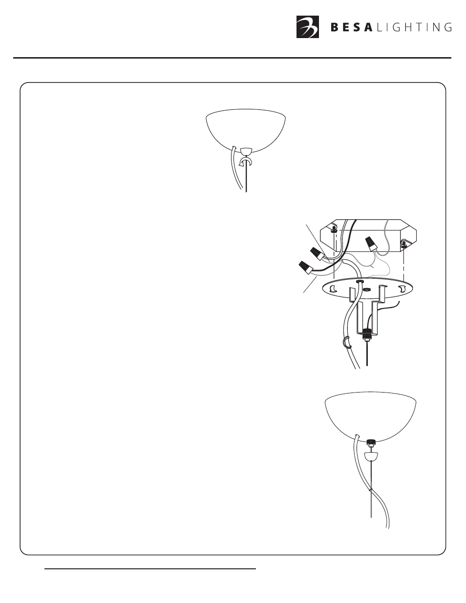
1. Carefully unpack parts. Remove the
Canopy (A) from the Mounting Plate
by unscrewing the Retainer (B).
Fully remove the Retainer from the
threaded nipple, then pull the canopy
from the Mounting Plate.
A
B
2. Prior to mounting fixture to ceiling, cord must be cut to length.
Measure the overall length of pendant drop, then add 25% to
allow for shaping of the cord. Cut off excess cord then strip back
outer jacket about 4” in length. To move the Strain Relief (I),
simply pinch together and slide down the cord.
3. Install the provided Mounting Screws (C) into the Outlet Box,
leaving 1/4” of threading as shown. Attach the bare copper fixture
ground wire and bare
(or green striped)
ground conductor from the
cord to the supply ground and secure with Wire Nut Connector (D).
Connect the cord conductors to the supply conductors with Wire Nut
Connectors (E) as shown: Cord conductor with white stripe to white
supply wire and clear cord conductor to black supply wire. Carefully
push wires and wire nuts back into outlet box.
When using the clear style cord, it is advised that
the installer confirm the polarity per instructions on
the next page.
4. Align the circular openings of the keyhole slots (F) of the Mounting
Plate (G) with the Mounting Screws. Push the Mounting Plate up over
the Outlet Box until tight to ceiling, then rotate the Mounting Plate
Counter-clockwise and secure with Mounting Screws.
5. To adjust pendant height, push the cable up through the Cable Grip (H)
to desired length. To lower pendant, push the Cable Grip up, which will
release the cable and allow it to be lowered. Trim the excess cable,
leaving about 6” above the Cable Grip. Position the Strain Relief close
to the Mounting Plate as shown.
6. Replace the Canopy as shown and secure with the Retainer. Tighten
the Retainer enough to hold the Canopy to the ceiling but do not overtighten.
The cord can now be shaped by positioning the clear Cord Rings (J) along
the cable as desired.
Overtightening can cause the Retainer to be difficult
to unscrew. If this occurs, usually rotating the canopy
counter-clockwise will help to unlock the Retainer.
C
D
E
F
G
Bare or Green Stripe
White
Stripe
H
I
J
Clear