Table 3-5, P7, lvds power supply jumper configuration, Table 3-6 – Artesyn COMX-CAR-210 Installation and Use (August 2014) User Manual
Page 32: P35, lvds power supply jumper configuration, Controls, leds, and connectors
Controls, LEDs, and Connectors
COMX-CAR-210 Installation and Use (6806800L14D)
32
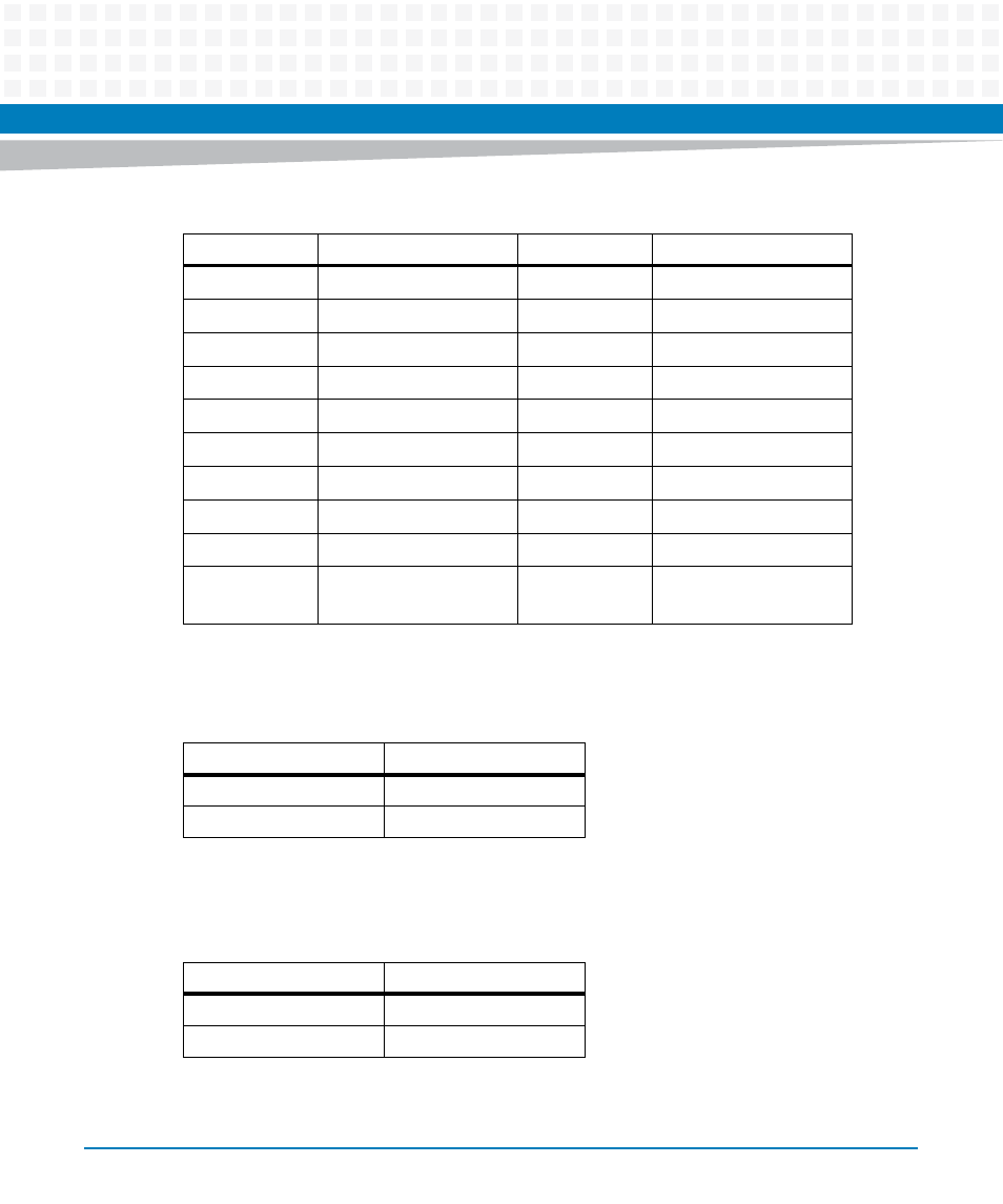
The 3V or 5V DC for the LVDS power supply is configured through the 3-pin jumper P7.
The 12V DC LVDS power supply is configured through the 3-pin header P35.
9
LVDSA_DATA1_N
10
LVDSB_DATA1_N
13
LVDSA_DATA2_P
14
LVDSB_DATA2_P
15
LVDSA_DATA2_N
16
LVDSB_DATA2_N
19
LVDSA_DATA3_P
20
LVDSB_DATA3_P
21
LVDSA_DATA3_N
22
LVDSB_DATA3_N
25
LVDSA_CLK_P
26
LVDSB_CLK_P
27
LVDSA_CLK_N
28
LVDSB_CLK_N
31
LVDS_I2C_CLK
32
LVDS_I2C_DATA
33,35,37,39
VDD (3.3V OR 5V)
36,38,40
VDD (12V)
5,
11,17,23,29
GND
6,12,18,24,30
,34
GND
Table 3-5 P7, LVDS Power Supply Jumper Configuration
Jumper Setting
Configuration
P7 (1-2)
3.3 V (Default)
P7 (2-3)
5V
Table 3-6 P35, LVDS Power Supply Jumper Configuration
Jumper Setting
Configuration
P35 (1-2)
Enable 12V
P35 (2-3)
NC (Default)
Table 3-4 P6, LVDS Connector Pin Definition (continued)
Pin
Signal
Pin
Signal
- ARTM-9405 16x10GbE Installation and Use Guide (May 2014) (64 pages)
- ATCA 7370 / ATCA 7370-S Installation and Use (January 2015) (256 pages)
- ATCA 7370 / ATCA 7370-S Installation and Use (September 2014) (254 pages)
- ARTM-831X Installation and Use (June 2014) (346 pages)
- ATCA-7350 - Integrating with Workbench User Guide (September 2014) (34 pages)
- ATCA-7350 Installation and Use (September 2014) (208 pages)
- ATCA-7365-CE Installation and Use (May 2014) (294 pages)
- ATCA-7365-CE Installation and Use (May 2014) (306 pages)
- ATCA-7365-CE Installation and Use (Jan 2015) (300 pages)
- ATCA-7368 Installation and Use (June 2014) (222 pages)
- ATCA-7475 Installation and Use (October 2014) (284 pages)
- ATCA-7480 Installation and Use (April 2015) (330 pages)
- ATCA-8330 Installation and Use (April 2015) (236 pages)
- ATCA-8320 Installation and Use (May 2014) (456 pages)
- ATCA-9305 User's Manual (May 2014) (270 pages)
- ATCA-9405 Installation and Use (October 2014) (168 pages)
- ATCA-F120 Installation and Use (August 2014) (122 pages)
- ATCA-F140 Installation and Use (September 2014) (138 pages)
- ATCA-MF106 Installation and Use (September 2014) (86 pages)
- Centellis-4440/AXP1440 Installation and Use (September 2014) (208 pages)
- Centellis 4410 (AXP-1410) Installation and Use (July 2014) (202 pages)
- Centellis 2100 Release 3.0 Installation and Use (March 2015) (192 pages)
- Centellis 2100 Release 3.0 Installation and Use (March 2015) (176 pages)
- Centellis 2000 User Card-10GE Installation and Use (May 2014) (54 pages)
- Centellis 2000 User Card-10GE with Telco Alarm Installation and Use (May 2014) (60 pages)
- COMX-P1022 Installation and Use (July 2014) (84 pages)
- COMX-P2020 Installation and Use (February 2015) (100 pages)
- COMX-CORE Series Installation and Use (August 2014) (128 pages)
- COMX-P2020 Installation and Use (July 2014) (100 pages)
- COMX-P4080-2G-ENP2 Installation and Use (August 2014) (70 pages)
- COMX-P4080 Installation and Use (August 2014) (126 pages)
- COMX-P40x0 ENP2 Installation and Use (August 2014) (130 pages)
- COMX-P40x0 ENP2 Installation and Use (January 2015) (140 pages)
- iVPX7225 RTM Installation and Use (April 2015) (56 pages)
- MITX-430/MITX-440-DVI-2E Installation and Use (August 2014) (118 pages)
- CPCI-6200 Installation and Use (May 2015) (234 pages)
- SCP-MITX-CORE-820-SM Installation and Use (August 2014) (132 pages)
- iVPX7225 Installation and Use (April 2015) (168 pages)
- MVME2502 Installation and Use (August 2014) (150 pages)
- MVME2502 Installation and Use (December 2014) (166 pages)
- MVME2500 VxWorks 6.8 AMP User Guide (August 2014) (40 pages)
- MVME2500 VxWorks 6.8 User Guide (April 2014) (44 pages)
- MVME3100 Single Board Computer Installation and Use (June 2014) (156 pages)
- MVME4100 Single Board Computer Installation and Use (June 2014) (136 pages)