Introduction – Artesyn COMX-CAR-210 Installation and Use (August 2014) User Manual
Page 16
Introduction
COMX-CAR-210 Installation and Use (6806800L14D)
16
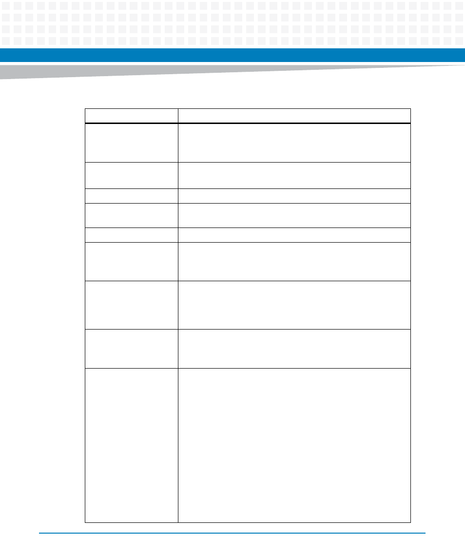
Serial ATA
Two seven-pin SATA-II ports
One twenty-two pin right-angle SSD connector
One twenty-two pin vertical power SATA connector
SPI
Two SPI sockets with BIOS. Disable headers are implemented.
One SF100 header to support the onboard program
Trusted Platform Module
One onboard TPM header
GPIO
Two GPIO headers. One is direct from the module, the other is from
the SIO WG83624UHG.
SMbus
One SMbus header from module for customer’s use
Power supply
One 24-pin ATX power header
One 4-pin ATX 12V header
One header for option to use 5V stand-by module or not
Hardware Monitor and
Controller
Three-channel voltage sensors: 5V, 3.3V and 12V
Two-channel temperature sensors: module and system
Three-channel fan speed control: one module fan and two sys-
tem fans
Supported module size
Compact form-factor
Basic form-factor
Extended form-factor
Standard compliance
COM Express Module Base Specification revision 2.0
PCI Express Mini Card Electromechanical Specification revision
1.0
PCI Express revision 1.1
PCI Local Bus revision 2.3
SMBus Version 2.0
Universal Host Controller Interface revision 1.1 (UHCI)
Enhanced Host Controller Interface specification for Universal
Serial Bus revision 1.0 (EHCI)
Serial ATA II: extensions to SATA 1.0, revision 1.0
VESA specification
PC 2001 compliance
ACPI
Table 1-1 Carrier Board Features (continued)
Feature
Description