3 leds, 4 connectors, 3 leds 3.4 connectors – Artesyn COMX-CAR-210 Installation and Use (August 2014) User Manual
Page 30: Table 3-2, Led function description, Controls, leds, and connectors
Controls, LEDs, and Connectors
COMX-CAR-210 Installation and Use (6806800L14D)
30
3.3
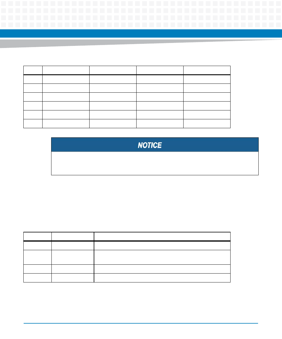
LEDs
The COMX-CAR-210 implemented some LEDs to indicate system status. The detailed function
description is listed below.
3.4
Connectors
This section lists down the information on the connectors of the COMX-CAR-210.
105
VCC_12V
VCC_12V
VCC_12V
VCC_12V
106
VCC_12V
VCC_12V
VCC_12V
VCC_12V
107
VCC_12V
VCC_12V
VCC_12V
VCC_12V
108
VCC_12V
VCC_12V
VCC_12V
VCC_12V
109
VCC_12V
VCC_12V
VCC_12V
VCC_12V
110
GND (FIXED)
GND (FIXED)
GND (FIXED)
GND (FIXED)
The signals group of PEG_TX [0:3] and PEG_RX [0:2] are routed to two PCIE Mux to switch
the signals between PEG and SDVO.
Table 3-1 COM EXPRESS Connector Pin Definition (continued)
Row
A
B
C
D
Table 3-2 LED function description
Location
Status
Description
D34
Type 2 Error
ON: Module does not comply with Type 2 spec
D26
Thermal Trip
ON: CPU is hot, system will shut down (only when the system is
running)
D21
Platform reset
ON: All power is OK and system is ready to start
D28
Suspend
ON: The module status is suspended
- ARTM-9405 16x10GbE Installation and Use Guide (May 2014) (64 pages)
- ATCA 7370 / ATCA 7370-S Installation and Use (January 2015) (256 pages)
- ATCA 7370 / ATCA 7370-S Installation and Use (September 2014) (254 pages)
- ARTM-831X Installation and Use (June 2014) (346 pages)
- ATCA-7350 - Integrating with Workbench User Guide (September 2014) (34 pages)
- ATCA-7350 Installation and Use (September 2014) (208 pages)
- ATCA-7365-CE Installation and Use (May 2014) (294 pages)
- ATCA-7365-CE Installation and Use (May 2014) (306 pages)
- ATCA-7365-CE Installation and Use (Jan 2015) (300 pages)
- ATCA-7368 Installation and Use (June 2014) (222 pages)
- ATCA-7475 Installation and Use (October 2014) (284 pages)
- ATCA-7480 Installation and Use (April 2015) (330 pages)
- ATCA-8330 Installation and Use (April 2015) (236 pages)
- ATCA-8320 Installation and Use (May 2014) (456 pages)
- ATCA-9305 User's Manual (May 2014) (270 pages)
- ATCA-9405 Installation and Use (October 2014) (168 pages)
- ATCA-F120 Installation and Use (August 2014) (122 pages)
- ATCA-F140 Installation and Use (September 2014) (138 pages)
- ATCA-MF106 Installation and Use (September 2014) (86 pages)
- Centellis-4440/AXP1440 Installation and Use (September 2014) (208 pages)
- Centellis 4410 (AXP-1410) Installation and Use (July 2014) (202 pages)
- Centellis 2100 Release 3.0 Installation and Use (March 2015) (192 pages)
- Centellis 2100 Release 3.0 Installation and Use (March 2015) (176 pages)
- Centellis 2000 User Card-10GE Installation and Use (May 2014) (54 pages)
- Centellis 2000 User Card-10GE with Telco Alarm Installation and Use (May 2014) (60 pages)
- COMX-P1022 Installation and Use (July 2014) (84 pages)
- COMX-P2020 Installation and Use (February 2015) (100 pages)
- COMX-CORE Series Installation and Use (August 2014) (128 pages)
- COMX-P2020 Installation and Use (July 2014) (100 pages)
- COMX-P4080-2G-ENP2 Installation and Use (August 2014) (70 pages)
- COMX-P4080 Installation and Use (August 2014) (126 pages)
- COMX-P40x0 ENP2 Installation and Use (August 2014) (130 pages)
- COMX-P40x0 ENP2 Installation and Use (January 2015) (140 pages)
- iVPX7225 RTM Installation and Use (April 2015) (56 pages)
- MITX-430/MITX-440-DVI-2E Installation and Use (August 2014) (118 pages)
- CPCI-6200 Installation and Use (May 2015) (234 pages)
- SCP-MITX-CORE-820-SM Installation and Use (August 2014) (132 pages)
- iVPX7225 Installation and Use (April 2015) (168 pages)
- MVME2502 Installation and Use (August 2014) (150 pages)
- MVME2502 Installation and Use (December 2014) (166 pages)
- MVME2500 VxWorks 6.8 AMP User Guide (August 2014) (40 pages)
- MVME2500 VxWorks 6.8 User Guide (April 2014) (44 pages)
- MVME3100 Single Board Computer Installation and Use (June 2014) (156 pages)
- MVME4100 Single Board Computer Installation and Use (June 2014) (136 pages)