Front panel, Rear panel – ARRIS WTM652 User Guide User Manual
Page 23
A
C
B
D
F
E
H
G
Se
cur
e
WL
AN
B
E
C
A
D
F H J
G I
23
Touchstone WTM652 Telephony Modem User’s Guide
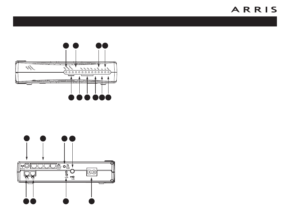
Front Panel
The front of the Telephony Modem has the following indicators:
A Battery: (WTM652G only) indicates the battery status.
B Telephone 1/2: indicates the status of each telephone line.
C Secure: indicates Wireless Protected Setup (WPS) is active.
D WLAN: indicates the status of the wireless LAN.
E LAN 1–4: indicates the status of each Ethernet port.
F Link: indicates Ethernet or wireless connectivity between the Telephony-
Modem and computers.
G Online: indicates internet data transmission status.
H US: indicates upstream connectivity.
I DS: indicates downstream connectivity.
J Power: indicates whether AC power is available to the unit.
Rear Panel
The rear of the Telephony Modem has the following connectors and controls:
A Tel 1 (A/B models): connector for the first phone line.
Tel 1/2 (G models): connector for the first phone line (or both lines of a
2-line phone).
B Tel 2: connector for the second phone line.
C Antenna: connector for the wireless antenna.
D Ethernet: for use with a computer LAN port.
E Router Reset button: resets the Ethernet and wireless ports without af-
fecting telephony service.
F TM Reset button: resets the Telephony Modem as if you power cycled the
unit. Use a pointed non-metallic object to press this button.
G Cable: connector for the coaxial cable.
H Power: connector for the power cord.