Figure 5 – wall mount-screw head dimensions – ARRIS SBG6580 User Guide User Manual
Page 20
Installing the Gateway
SURFboard® SBG6580 Wireless Cable Modem Gateway • User Guide
9
365-095-25397-x.1
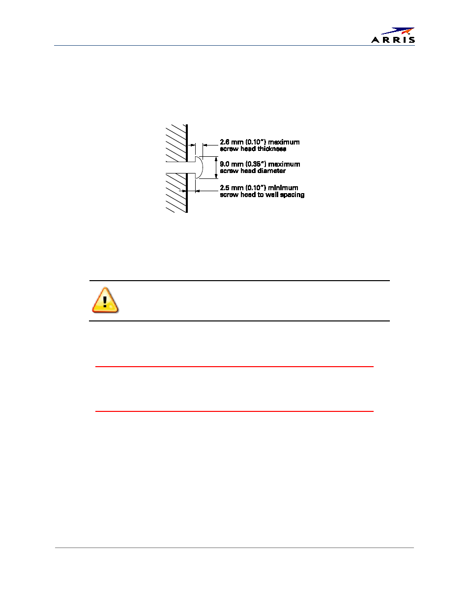
ο Two M3.5 (#6) screws with a flat underside and maximum screw head diameter of 9.0 mm to
mount the SBG6580.
Note: Contact a qualified installer to determine the appropriate screw length needed for mounting a
gateway.
See the dimensioned view below for the spacing needed between the screw heads and wall:
Figure 5 – Wall Mount-Screw Head Dimensions
Note: If possible, mount the SBG6580 to concrete, masonry, wooden stud, or some other solid wall material.
Use anchor bolts if necessary (for example, if you mount the unit on drywall).
Before drilling holes in the wall, check the structure for potential damage
to water, gas, or electrical lines.
Perform the following steps to wall mount the SBG6580:
1. Use the
as a guide for drilling holes in the wall (see Figure 6).
WARNING!
The wall mounting template is intended as a sample representation of the
SBG6580 side view. The mounting hole dimensions shown on the template may not be
accurate. BEFORE drilling any holes in the wall, check to ensure that your measurements match
the hole markings on the side of the SBG6580.
There must be .10 inch (2.5 mm) between the wall and underside of the screw head.
2. Select an appropriate depth and diameter to drill the holes to a depth of at least 1½ inches (3.8 cm).
Note: The installer must determine the depth of the hole, the necessary hardware and must be careful to
select the appropriate depth and diameter.
3. Attach the SBG6580 to the two screws on the wall. Check that it is securely mounted.
4. Reconnect the coaxial and Ethernet cables.
5. Re-plug the power cord into the SBG6580 and the electrical outlet.
6. Arrange the cables to prevent any safety hazards.
7. Check that the gateway is still securely mounted on the wall.